Secondary
Chilled Water Loop – Plate Heat Exchanger[LINK]
The Secondary Cooling system is constructed by using a
PlantLoop
object, the working fluid in this loop is water. It uses one
side of a plate heat exchanger (modeled using a HeatExchanger:FluidToFluid
object) to supply chilled water to a cooling coil (modeled by
using a Coil:Cooling:DetailedGeometry object).
Therefore, the supply side of the loop contains the heat
exchanger and the demand side contains the cooling coil. The
loop is operated by using plant equipment operation schemes,
and schedules. Refer to Figure 103 for a simple diagram of
the secondary chilled water loop.
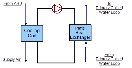
Figure 103 - Simple line diagram for the secondary chilled
water loop
This series of flowcharts serve as a guide for identifying
and inputting the secondary chilled water loop and its
components into the input file. The EnergyPlus line diagram
for this loop is provided in Figure 104. A simple flowchart
for the separation of the half loops is provided in Figure
105.
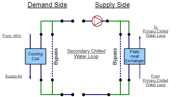
Figure 104 - EnergyPlus line diagram for the secondary
chilled water loop
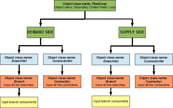
Figure 105 - Simple flow chart for separation on half loops
in the secondary chilled water loop
Secondary
Chilled Water Loop Supply Side Loop Construction[LINK]
The main components on the supply side half loop for the
Secondary Cooling System are the plate heat exchanger that
supplies the chilled water and the variable speed pump that
circulates the chilled water through the loop. The variable
speed pump (named ‘CW Sec Circ Pump’) is the secondary pump in
the primary/secondary pumping setup. This half loop supplies
chilled water to a cooling coil on the demand side half loop.
The supply side half loop contains four components, four
branches, eight nodes, and one splitter-mixer pair. The
EnergyPlus line diagram for the secondary chilled water loop
supply side is provided in Figure 106. The flowchart for
supply side branches and components is provided in Figure 107.
The flowchart for supply side connectors is provided in Figure
108.
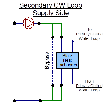
Figure 106 - EnergyPlus line diagram for the supply side of
the secondary chilled water loop
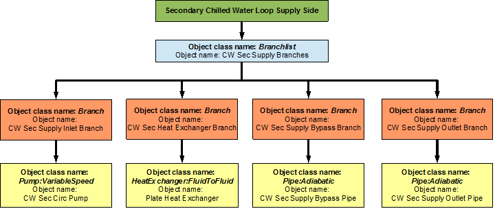
Figure 107 – Flowchart for secondary chilled water loop
supply side branches and components
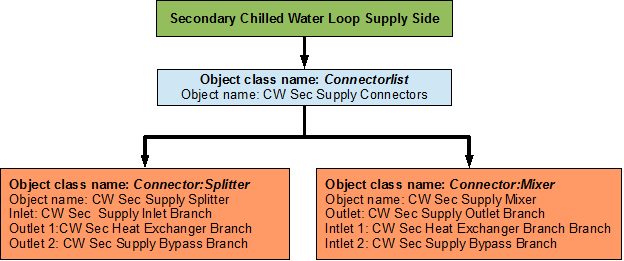
Figure 108 – Flowchart for secondary chilled water loop
supply side connectors
Secondary
Chilled Water Loop Demand Side Loop Construction[LINK]
The main component on the demand side half loop is the
Cooling Coil that cools the air in the building by using the
chilled water that is supplied by the plate heat exchanger.
This side of the loop also has eight nodes, four components,
four branches, and one splitter-mixer pair. An EnergyPlus
schematic for the demand side is provided in Figure 109. The
flowchart for demand side branch definition is provided in
Figure 110. The flowchart for the demand side connectors is
provided in Figure 111.
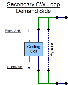
Figure 109 - EnergyPlus line diagram for the demand side of
the secondary chilled water loop
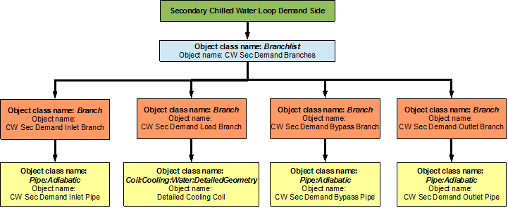
Figure 110 – Flowchart for secondary chilled water loop
demand side branches and components
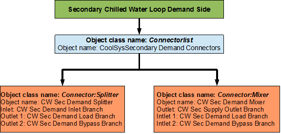
Figure 111 – Flowchart for secondary chilled water loop
demand side connectors
Flowcharts
for secondary chilled water loop Controls[LINK]
The secondary chilled water loop is operated by using
set-points, plant equipment operation schemes and
schedules.
Secondary
Chilled Water Loop Schedules[LINK]
The flowchart for Primary Cooling loop schedule definition
is provided in Figure 112. The Secondary Cooling loop uses two
different schedules to operate properly. ON is a
compact schedule that keeps the plate heat exchanger running
at all times of the day, this compact schedule uses a
continuous ScheduleTypeLimit (Fraction)
which defines that the value of On is 1 and that of Off is 0.
This plant loop also uses another compact schedule named
CW Sec Loop Temp Schedule declares that the outlet
temperature of the Secondary Cooling loop should be 6.67
degrees Celsius at any time; this schedule is used by the
setpoint manager (CW Sec Loop Setpoint Manager). This
schedule uses a schedule type limit named
Temperature, which defines the loop upper and lower
temperature limits.
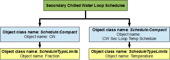
Figure 112 – Flowchart for secondary chilled water loop
schedules
Secondary
Chilled Water Loop Plant Equipment Operation Schemes[LINK]
The PlantEquipmentOperationschemes object uses the
ON schedule and the CW Sec Operation Scheme
objects to set the range of the demand loads for which the
heat exchanger is operated during the simulation period. A
flowchart detailing the secondary chilled water loop plant
equipment operation schemes is provided in Figure 113.
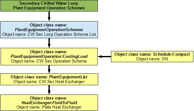
Figure 113 – Flowchart for secondary chilled water loop
plant equipment operation schemes
Secondary
Chilled Water Loop Setpoints[LINK]
The CW Sec Loop Setpoint Manager uses the CW
Sec Loop Temp Schedule to set a temperature control point
at the CW Sec Supply Outlet Node. This setpoint
allows the program to control the temperature at the node by
operating the components in the Secondary Cooling loop. A
flowchart for Secondary Cooling loop setpoints is provided in
Figure 114.
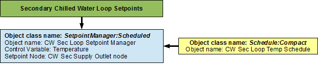
Figure 114 – Flowchart for secondary chilled water loop
setpoints
Secondary Chilled
Water Loop Sizing[LINK]
The secondary chilled water loop is sized such a way that
the design loop exit temperature is 6.67 degrees Celsius, and
the loop design temperature difference is 5 degrees Celsius. A
flowchart for the chilled water loop sizing is provided in
Figure 115.
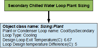
Figure 115 – Flowchart for secondary chilled water loop
sizing

Secondary Chilled Water Loop – Plate Heat Exchanger[LINK]
The Secondary Cooling system is constructed by using a PlantLoop object, the working fluid in this loop is water. It uses one side of a plate heat exchanger (modeled using a HeatExchanger:FluidToFluid object) to supply chilled water to a cooling coil (modeled by using a Coil:Cooling:DetailedGeometry object). Therefore, the supply side of the loop contains the heat exchanger and the demand side contains the cooling coil. The loop is operated by using plant equipment operation schemes, and schedules. Refer to Figure 103 for a simple diagram of the secondary chilled water loop.
Figure 103 - Simple line diagram for the secondary chilled water loop
Flowcharts for the Secondary Chilled Water Loop Input Process[LINK]
This series of flowcharts serve as a guide for identifying and inputting the secondary chilled water loop and its components into the input file. The EnergyPlus line diagram for this loop is provided in Figure 104. A simple flowchart for the separation of the half loops is provided in Figure 105.
Figure 104 - EnergyPlus line diagram for the secondary chilled water loop
Figure 105 - Simple flow chart for separation on half loops in the secondary chilled water loop
Secondary Chilled Water Loop Supply Side Loop Construction[LINK]
The main components on the supply side half loop for the Secondary Cooling System are the plate heat exchanger that supplies the chilled water and the variable speed pump that circulates the chilled water through the loop. The variable speed pump (named ‘CW Sec Circ Pump’) is the secondary pump in the primary/secondary pumping setup. This half loop supplies chilled water to a cooling coil on the demand side half loop. The supply side half loop contains four components, four branches, eight nodes, and one splitter-mixer pair. The EnergyPlus line diagram for the secondary chilled water loop supply side is provided in Figure 106. The flowchart for supply side branches and components is provided in Figure 107. The flowchart for supply side connectors is provided in Figure 108.
Figure 106 - EnergyPlus line diagram for the supply side of the secondary chilled water loop
Figure 107 – Flowchart for secondary chilled water loop supply side branches and components
Figure 108 – Flowchart for secondary chilled water loop supply side connectors
Secondary Chilled Water Loop Demand Side Loop Construction[LINK]
The main component on the demand side half loop is the Cooling Coil that cools the air in the building by using the chilled water that is supplied by the plate heat exchanger. This side of the loop also has eight nodes, four components, four branches, and one splitter-mixer pair. An EnergyPlus schematic for the demand side is provided in Figure 109. The flowchart for demand side branch definition is provided in Figure 110. The flowchart for the demand side connectors is provided in Figure 111.
Figure 109 - EnergyPlus line diagram for the demand side of the secondary chilled water loop
Figure 110 – Flowchart for secondary chilled water loop demand side branches and components
Figure 111 – Flowchart for secondary chilled water loop demand side connectors
Flowcharts for secondary chilled water loop Controls[LINK]
The secondary chilled water loop is operated by using set-points, plant equipment operation schemes and schedules.
Secondary Chilled Water Loop Schedules[LINK]
The flowchart for Primary Cooling loop schedule definition is provided in Figure 112. The Secondary Cooling loop uses two different schedules to operate properly. ON is a compact schedule that keeps the plate heat exchanger running at all times of the day, this compact schedule uses a continuous ScheduleTypeLimit (Fraction) which defines that the value of On is 1 and that of Off is 0. This plant loop also uses another compact schedule named CW Sec Loop Temp Schedule declares that the outlet temperature of the Secondary Cooling loop should be 6.67 degrees Celsius at any time; this schedule is used by the setpoint manager (CW Sec Loop Setpoint Manager). This schedule uses a schedule type limit named Temperature, which defines the loop upper and lower temperature limits.
Figure 112 – Flowchart for secondary chilled water loop schedules
Secondary Chilled Water Loop Plant Equipment Operation Schemes[LINK]
The PlantEquipmentOperationschemes object uses the ON schedule and the CW Sec Operation Scheme objects to set the range of the demand loads for which the heat exchanger is operated during the simulation period. A flowchart detailing the secondary chilled water loop plant equipment operation schemes is provided in Figure 113.
Figure 113 – Flowchart for secondary chilled water loop plant equipment operation schemes
Secondary Chilled Water Loop Setpoints[LINK]
The CW Sec Loop Setpoint Manager uses the CW Sec Loop Temp Schedule to set a temperature control point at the CW Sec Supply Outlet Node. This setpoint allows the program to control the temperature at the node by operating the components in the Secondary Cooling loop. A flowchart for Secondary Cooling loop setpoints is provided in Figure 114.
Figure 114 – Flowchart for secondary chilled water loop setpoints
Secondary Chilled Water Loop Sizing[LINK]
The secondary chilled water loop is sized such a way that the design loop exit temperature is 6.67 degrees Celsius, and the loop design temperature difference is 5 degrees Celsius. A flowchart for the chilled water loop sizing is provided in Figure 115.
Figure 115 – Flowchart for secondary chilled water loop sizing
Documentation content copyright © 1996-2026 The Board of Trustees of the University of Illinois and the Regents of the University of California through the Ernest Orlando Lawrence Berkeley National Laboratory. All rights reserved. EnergyPlus is a trademark of the US Department of Energy.
This documentation is made available under the EnergyPlus Open Source License v1.0.