Setpoint Managers[LINK]
Setpoint Managers are one of the high-level control
constructs in EnergyPlus. A Setpoint Manager is able to access
data from any of the HVAC system nodes and use this data to
calculate a setpoint (usually a temperature setpoint) for one
or more other HVAC system nodes. Setpoints are then used by
Controllers as a goal for their control actions.
Setpoint managers are executed at the start of each HVAC
time step, and they reside outside the HVAC system iteration
loops. Thus, the Setpoint Managers are executed once per HVAC
time step, and they use previous time step information (except
for zone load) to calculate their setpoints.
All temperatures in the following descriptions are in
degrees C, loads are in Watts, mass flow rates are in
kg/s.
The input object SetpointManager:Scheduled
provides the simplest setpoint manager that allows the user to
specify a seasonal (or other) scheduled reset, for example, of
the supply air temperature setpoint.
where  is the supply air
temperature setpoint and
is the supply air
temperature setpoint and  is
the current value (°C) from the user input temperature
schedule. In this case,
is
the current value (°C) from the user input temperature
schedule. In this case,  will
be applied to the node or nodes specified in the input object
SetpointManager:Scheduled.
There are a number of other types of setpoints that can be
set, by choosing different control variables in the object,
including:
will
be applied to the node or nodes specified in the input object
SetpointManager:Scheduled.
There are a number of other types of setpoints that can be
set, by choosing different control variables in the object,
including:
Maximum temperature of fluid at node (°C)
Minimum temperature of fluid at node (°C)
Humidity ratio of fluid at node (kg water/ kg dry air)
Maximum humidity ratio of fluid at node (kg water/ kg dry
air)
Minimum humidity ratio of fluid at node (kg water/ kg dry
air)
Mass flow rate of fluid at node (kg/s)
Maximum mass flow rate of fluid at node (kg/s)
Minimum mass flow rate of fluid at node (kg/s)
Outdoor Air Reset[LINK]
The input object SetpointManager:OutdoorAirReset
provides a setpoint manager that implements an outdoor air
reset strategy for the supply air temperature. The user
defines a reset rule for this strategy by specifying two
setpoint temperatures at two outside drybulb temperatures.
Generally the lower setpoint temperature is matched with the
higher drybulb temperature and the higher setpoint temperature
with the lower drybulb temperature. The user can specify two
reset rules and schedule their usage. A schedule value of 1
indicates use of the 1st rule; 2 indicates use of the 2nd.
IF SchedVal =2
otherwise
 .
.
If  and
and  then
then
If  then
then
if  then
then
otherwise
otherwise
 .
.
 will be
applied to the node or nodes specified in the SetpointManager:OutdoorAirReset
object input.
will be
applied to the node or nodes specified in the SetpointManager:OutdoorAirReset
object input.
Single Zone
Reheat Heating and Cooling[LINK]
The input object SetpointManager:SingleZone:Reheat
provides a setpoint manager that is used to implement a
variable supply air setpoint temperature in which the setpoint
is varied each timestep to meet the heating or cooling load in
a control zone. The manager operates in the following
manner.
where  is the control zone
temperature,
is the control zone
temperature,  is the zone
load (greater than zero for heating, less than zero for
cooling),
is the zone
load (greater than zero for heating, less than zero for
cooling),  is the zone supply
air mass flow rate, and
is the zone supply
air mass flow rate, and  is
the specific heat of air. If
is
the specific heat of air. If  is very small (
 kg/s)
kg/s)  is set equal to
  if the control zone has a cooling
load and to
if the control zone has a cooling
load and to  if the control
zone has a heating load.
if the control
zone has a heating load.  is
the user specified minimum setpoint and
is
the user specified minimum setpoint and  is the user specified maximum
setpoint.
is the user specified maximum
setpoint.  will be applied to
the node or nodes specified in the SetpointManager:SingleZone:Reheat
object input.
will be applied to
the node or nodes specified in the SetpointManager:SingleZone:Reheat
object input.
Single Zone Heating
Only[LINK]
The input object SetpointManager:SingleZone:Heating
provides a model that detects the control zone load to meet
the current heating setpoint (Report Variable “Zone Predicted
Sensible Load to Heating Setpoint Heat Transfer Rate [W]”,
zone inlet node flow rate, and zone node temperature, and
calculates a setpoint temperature for the supply air that will
satisfy the zone heating load for the control zone. “Zone
Predicted Sensible Load to Heating Setpoint Heat Transfer Rate
[W]” > 0 indicates a heating load. The following rules are
applied:
If there is no zone heating load, then the setpoint is set
at the specified minimum supply air temperature.
If there is a zone heating load and the zone supply mass
flow rate is less than 0.001 kg/s, then the setpoint is set at
the specified maximum supply air temperature.
If there is a zone heating load and the zone supply mass
flow rate is greater than 0.001 kg/s, then the setpoint is set
calculated as follows:
SetPoint = ZoneTemp +
ZoneLoadtoHeatSP/(CpAir*ZoneMassFlow)
where:
SetPoint = Setpoint temperature applied to the
specified setpoint node(s)
ZoneTemp = Current zone temperature
ZoneLoadtoHeatSP = Zone
heating load (Report Variable **” Zone
Predicted Sensible Load to Heating Setpoint Heat Transfer Rate
[W]“)
CpAir = Specific heat of zone supply air
ZoneMassFlow = Zone
supply air mass flow rate
Single Zone Cooling
Only[LINK]
The input object SetpointManager:SingleZone:Cooling
provides a model that detects the control zone load to meet
the current cooling setpoint (Report Variable “Zone Predicted
Sensible Load to Cooling Setpoint Heat Transfer Rate [W]”,
zone inlet node flow rate, and zone node temperature, and
calculates a setpoint temperature for the supply air that will
satisfy the zone cooling load for the control zone. “Zone
Predicted Sensible Load to Cooling Setpoint Heat Transfer Rate
[W]” < 0 indicates a cooling load. The following rules are
applied:
If there is no zone cooling load, then the setpoint is set
at the specified maximum supply air temperature.
If there is a zone cooling load and the zone supply mass
flow rate is less than 0.001 kg/s, then the setpoint is set at
the specified minimum supply air temperature.
If there is a zone cooling load and the zone supply mass
flow rate is greater than 0.001 kg/s, then the setpoint is set
calculated as follows:
SetPoint = ZoneTemp +
ZoneLoadtoCoolSP/(CpAir*ZoneMassFlow)
where:
SetPoint = Setpoint temperature applied to the
specified setpoint node(s)
ZoneTemp = Current zone temeprature
ZoneLoadtoCoolSP = Zone
cooling load (Report Variable “Zone Predicted Sensible Load to
Cooling Setpoint Heat Transfer Rate [W]”)
CpAir = Specific heat of zone supply air
ZoneMassFlow = Zone
supply air mass flow rate
Single Zone Minimum
Humidity[LINK]
The input object SetpointManager:SingleZone:Humidity:Minimum
provides a model where the zone moisture load from
ZoneTempPredictorCorrector (via DataZoneEnergyDemands) is used
to calculate the minimum/maximum supply air humidity ratio
needed to meet minimum/maximum zone relative humidity
requirement. For the Max setpoint manager is currently used in
Controller:WaterCoil,
when the control variable “TemperatureAndHumidityRatio”. A
negative MoistureLoad means a dehumidification load for the
coil controller. This could be used for any system.
Single Zone Maximum
Humidity[LINK]
The input object SetpointManager:SingleZone:Humidity:Maximum
provides a setpoint manager that allows the control of high
air humidity levels in a single zone. This setpoint manager,
used in conjunction with object ZoneControl:Humidistat,
detects the air humidity level in a single control zone and
uses air/moisture mass balances to calculate the supply air
humidity ratio needed to maintain the zone relative humidity
at or below a given setpoint. The calculated supply air
humidity ratio is then entered as a setpoint on a designated
supply air stream node. A dehumidification component placed
upstream of this node can then use the humidity ratio setpoint
to control its moisture removal rate (e.g. desiccant
dehumidifiers). In the case of a chilled water coil which is
used for both temperature and high humidity control, this
setpoint manager works in conjunction with a Controller:WaterCoil
object to determine the minimum supply air temperature
required to meet both the temperature (sensible) and humidity
(latent) load in the control zone. (Ref:
Controller:WaterCoil).
Model Description[LINK]
The user must input the required information according to
the IO Reference Manual (ref:
SetpointManager:SingleZone:Humidity:Maximum). Specific inputs
include an object name, control variable (HumidityRatio), name
of the schedule defining the maximum relative humidity for the
control zone, setpoint node name or list, and the zone air
node name associated with the control zone (ref:
ZoneHVAC:EquipmentConnections). The schedule name must refer
to a valid schedule type (range 0-1) and contain values of
fractional relative humidity.
This setpoint manager first converts the desired relative
humidity setpoint for the control zone to humidity ratio based
on the control zone dry-bulb temperature, the scheduled
maximum relative humidity setpoint and outdoor barometric
pressure.
where:
 = humidity ratio
setpoint, kg H2O/kg air
= humidity ratio
setpoint, kg H2O/kg air
PsyWFnTdbRHPb = EnergyPlus psychrometric function, returns
humidity ratio as a function of dry-bulb temperature, relative
humidity, and barometric pressure
 = dry-bulb temperature in
the control zone, °C
= dry-bulb temperature in
the control zone, °C
 = maximum relative
humidity setpoint, fraction
= maximum relative
humidity setpoint, fraction
 = outdoor barometric
pressure, Pa
= outdoor barometric
pressure, Pa
The model then calculates the supply air humidity ratio
required to reduce the control zone relative humidity to the
desired level. Using the humidity ratio setpoint ( ) calculated above,
where:
 = maximum supply air
humidity ratio setpoint, kg H2O/kg air
= maximum supply air
humidity ratio setpoint, kg H2O/kg air
 = control zone latent
load, kg H2O/s (calculated by Zone
Control:Humidistat)
= control zone latent
load, kg H2O/s (calculated by Zone
Control:Humidistat)
 = control zone mass flow
rate, kg/s
= control zone mass flow
rate, kg/s
All setpoint managers are executed at the beginning of the
simulation time step. Therefore, the calculated setpoint is
based on the resulting control zone air temperature and air
mass flow rate for the previous simulation time step.
The maximum supply air humidity ratio setpoint is placed on
the node(s) specified in the input for this object (using node
property Humidity Ratio Maximum).
The input object SetpointManager:MixedAir
provides a setpoint manager that takes an already established
setpoint (usually the supply air outlet node setpoint
temperature), subtracts the supply fan heat gain, and applies
the result as the setpoint temperature at the mixed air node
(or any other node the user specifies).
Outdoor Air Pretreat[LINK]
The input object SetpointManager:OutdoorAirPretreat
provides a setpoint manager that is meant to be used in
conjunction with an OutdoorAir:Mixer.
The outdoor air pretreat setpoint manager is used to establish
a temperature or humidity ratio setpoint in the outdoor air
stream flowing into the outdoor air stream node of an outdoor
air mixer. This setpoint manager determines the required
setpoint in the outdoor air stream to produce the reference
setpoint in the mixed air stream after mixing with return air.
For example, if the temperature setpoint at the mixed air node
is 15C, the return air temperature is 20C, and the outdoor air
flow fraction is 0.5, the outdoor air pretreat setpoint would
be set to 10C. This setpoint manager references four
user-specified nodes to obtain the following values:
- Reference setpoint node – desired mixed flow condition =
RefNodeSetPoint
- Mixed air stream node – mixed air flow rate =
MixedOutNodeMassFlowRate
- Outdoor air stream node – outdoor air flow rate =
OAInNodeMassFlowRate
- Return air stream node – return air condition =
ReturnInValue
The following calculations are used to determine the new
setpoint value (SetPoint):
OAFraction = OAInNodeMassFlowRate /
MixedOutNodeMassFlowRate
SetPoint = ReturnInValue + (RefNodeSetPoint -
ReturnInValue)/OAFraction
Depending on the specified control variable type, the
setpoints and conditions may be humidity ratio (max or min) or
temperature. Note that zero is not allowed as the computed
setpoint humidity ratio, because zero is used as a special
value to indicate that no humidification or dehumidification
is needed. If the reference humidity ratio setpoint value is
zero, the zero value will be passed directly to the setpoint
Node(s).
Warmest Zone Supply Air
Reset[LINK]
The input object SetpointManager:Warmest
provides a setpoint manager that attempts to establish a
supply air setpoint that will meet the cooling load of the
zone needing the coldest air at the maximum zone supply air
flowrate. The algorithm loops over all the zones that the
system can cool and calculates
Note that for cooling  The
lowest
The
lowest  is chosen as
  .
.  is constrained to be less than or
equal to the maximum setpoint temperature (user input) and
greater than or equal to the minimum setpoint temperature
(user input). If the sum of the zone cooling loads is very
small, the setpoint temperature is set to the maximum.
is constrained to be less than or
equal to the maximum setpoint temperature (user input) and
greater than or equal to the minimum setpoint temperature
(user input). If the sum of the zone cooling loads is very
small, the setpoint temperature is set to the maximum.  will be applied to the node or
nodes specified in the SetpointManager:Warmest
object input.
will be applied to the node or
nodes specified in the SetpointManager:Warmest
object input.
Coldest Zone Supply Air
Reset[LINK]
The input object SetpointManager:Coldest
provides a setpoint manager that attempts to establish a
supply air setpoint that will meet the heating load of the
zone needing the warmest air at the maximum zone supply air
flowrate. The algorithm loops over all the zones that the
system can heat and calculates
Note that for heating 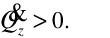 The
highest
The
highest  is chosen as
  .
.  is constrained to be less than or
equal to the maximum setpoint temperature (user input) and
greater than or equal to the minimum setpoint temperature
(user input). If the sum of the zone heating loads is very
small, the setpoint temperature is set to the minimum.
is constrained to be less than or
equal to the maximum setpoint temperature (user input) and
greater than or equal to the minimum setpoint temperature
(user input). If the sum of the zone heating loads is very
small, the setpoint temperature is set to the minimum.  will be applied to the node or
nodes specified in the SetpointManager:Coldest
object input.
will be applied to the node or
nodes specified in the SetpointManager:Coldest
object input.
Return Air Bypass Flow[LINK]
The input object SetpointManager:ReturnAirBypassFlow
provides a setpoint manager that sets the air flow rate in a
bypass duct such that when the bypassed and non-bypassed air
are mixed the resutant air stream will be at the
user-specified setpoint temperature.
The user specifies the desired setpoint temperature
Tset~~through a input temperature
schedule.
This temperature is modified to account for any potential
fan heat gain:
Here  is the temperature
at the air loop outlet node and
is the temperature
at the air loop outlet node and  is the temperature at the outlet
node of the bypass – nonbypass air mixer. Depending on the
system configuration these may be the same node. Then
is the temperature at the outlet
node of the bypass – nonbypass air mixer. Depending on the
system configuration these may be the same node. Then
where  is the total supply
air flowrate in kg/s sent to the zones,
is the total supply
air flowrate in kg/s sent to the zones,  is the nonbypassed air flowrate
(the conditioned air),
is the nonbypassed air flowrate
(the conditioned air),  is
the corresponding temperature just before mixing with the
bypassed air, and
is
the corresponding temperature just before mixing with the
bypassed air, and  is the
temperature of the bypassed (unconditioned) air. The resulting
is the
temperature of the bypassed (unconditioned) air. The resulting
 is the mass flow rate
setpoint for the bypass air branch.
is the mass flow rate
setpoint for the bypass air branch.
Warmest Temp Flow[LINK]
The input object SetpointManager:WarmestTemperatureFlow
provides a setpoint manager that attempts to establish a
supply air setpoint that will meet the cooling load of the
zone needing the coldest air at the maximum zone supply air
flowrate. The supply air temperature setpoint is established
by SetpointManager:WarmestTemperatureFlow
using one of two strategies: ‘Temp First’ sets the supply air
temperature to the highest temperature that will meet the
cooling load of the coolest zone at minimum cfm. ‘Flow First’
sets the supply air temperature to the highest temperature
that will meet the cooling load of the warmest zone at maximum
cfm. ‘Temp First’ gives higher priority to reducing fan energy
whereas ‘Flow First’ gives higher priority to reducing chiller
energy.
The algorithm loops over all the zones that the system can
cool and calculates according to strategy:
Temp First:
Flow First:
where  is the minimum air
flow rate to the zone produced by reducing the capacity of the
supply fan or by reducing the opening of the damper in the
terminal box, if present, and
is the minimum air
flow rate to the zone produced by reducing the capacity of the
supply fan or by reducing the opening of the damper in the
terminal box, if present, and  is the design air flow rate to
the zone.
is the design air flow rate to
the zone.
Note that for cooling  The
lowest
The
lowest  is chosen as
  .
.  is constrained to be less than or
equal to the maximum setpoint temperature (user input) and
greater than or equal to the minimum setpoint temperature
(user input). If the unconstrained value of
is constrained to be less than or
equal to the maximum setpoint temperature (user input) and
greater than or equal to the minimum setpoint temperature
(user input). If the unconstrained value of  is less than the minimum setpoint
temperature and there are no VAV terminal boxes, the fan
capacity is increased so as to meet the zone cooling loads
with the constrained value of
is less than the minimum setpoint
temperature and there are no VAV terminal boxes, the fan
capacity is increased so as to meet the zone cooling loads
with the constrained value of  :
:
This is more likely to occur in the ‘Temp First’ case. If
the sum of the zone cooling loads is very small, the setpoint
temperature is set to the maximum.  will be applied to the node or
nodes specified in the SetpointManager:WarmestTemperatureFlow
object input.
will be applied to the node or
nodes specified in the SetpointManager:WarmestTemperatureFlow
object input.
Multizone Heating
Average[LINK]
The input object SetpointManager:MultiZone:Heating:Average
provides a setpoint manager that attempts to establish a
supply air heating setpoint that will meet the heating load of
multiple zones served by an HVAC air loop. The algorithm
aggregates the predicted heating loads for all controlled
zones served by an air loop (i.e., zones that have a
thermostat object), and calculates the multizone average
supply air heating setpoint temperature as follows:
IF (  > 0 ) THEN
END IF
where,
 = average supply air
setpoint temperature (°C)
= average supply air
setpoint temperature (°C)
 = number of controlled
zones (i.e., zones that contain thermostat objects) served by
the air loop (-)
= number of controlled
zones (i.e., zones that contain thermostat objects) served by
the air loop (-)
 = sensible heating load
required to reach the zone air temperature setpoint for the
jth controlled zone at current time step
(W)
= sensible heating load
required to reach the zone air temperature setpoint for the
jth controlled zone at current time step
(W)
 = air mass flow rate
being supplied by the air loop to the jth
controlled zone, lagged by one HVAC simulation time step
(kg/s)
= air mass flow rate
being supplied by the air loop to the jth
controlled zone, lagged by one HVAC simulation time step
(kg/s)
 = specific heat of supply
air for the jth controlled zone (J/kg-K)
= specific heat of supply
air for the jth controlled zone (J/kg-K)
 = air node temperature
for the jth controlled zone (°C)
= air node temperature
for the jth controlled zone (°C)
 = average zone air node
temperature weighted by the heat capacity rate of the supply
air streams for the controlled zones served by the air loop
(°C)
= average zone air node
temperature weighted by the heat capacity rate of the supply
air streams for the controlled zones served by the air loop
(°C)
 = total number of zones
served by the air loop (-)
= total number of zones
served by the air loop (-)
Note that for heating  The
average supply air setpoint temperature
The
average supply air setpoint temperature  is constrained to be less than or
equal to the maximum setpoint temperature (user input) and
greater than or equal to the minimum setpoint temperature
(user input). If the sum of the zone sensible heating loads is
extremely small (i.e., no heating load), the setpoint
temperature is set to the minimum. will be applied to the setpoint
node or nodes specified in the SetpointManager:MultiZone:Heating:Average
object.
is constrained to be less than or
equal to the maximum setpoint temperature (user input) and
greater than or equal to the minimum setpoint temperature
(user input). If the sum of the zone sensible heating loads is
extremely small (i.e., no heating load), the setpoint
temperature is set to the minimum. will be applied to the setpoint
node or nodes specified in the SetpointManager:MultiZone:Heating:Average
object.
Multizone Cooling
Average[LINK]
The input object SetpointManager:MultiZone:Cooling:Average
provides a setpoint manager that attempts to establish a
supply air cooling setpoint that will meet the cooling load of
multiple zones served by an HVAC air loop. The algorithm
aggregates the predicted cooling loads for all controlled
zones served by an air loop (i.e., zones that have a
thermostat object), and calculates the multizone average
supply air cooling setpoint temperature as follows:
IF ( < 0 ) THEN
END IF
Note that for cooling  The
average supply air setpoint temperature is constrained to be less than or
equal to the maximum setpoint temperature (user input) and
greater than or equal to the minimum setpoint temperature
(user input). If the sum of the zone sensible cooling loads is
extremely small (i.e., no cooling load), the setpoint
temperature is set to the maximum. will be applied to the setpoint
node or nodes specified in the SetpointManager:MultiZone:Cooling:Average
object.
The
average supply air setpoint temperature is constrained to be less than or
equal to the maximum setpoint temperature (user input) and
greater than or equal to the minimum setpoint temperature
(user input). If the sum of the zone sensible cooling loads is
extremely small (i.e., no cooling load), the setpoint
temperature is set to the maximum. will be applied to the setpoint
node or nodes specified in the SetpointManager:MultiZone:Cooling:Average
object.
Multizone Minimum
Humidity Average[LINK]
The input object SetpointManager:MultiZone:MinimumHumidity:Average
provides a setpoint manager that attempts to establish a
supply air minimum humidity ratio setpoint that will meet the
humidification load of multiple zones served by an HVAC air
loop. This setpoint manager, used in conjunction with object
ZoneControl:Humidistat,
detects the air humidity level for all controlled zones served
by an air loop (i.e., zones that have a humidistat object with
a humidifying setpoint schedule), and uses moisture mass
balances to calculate the average supply air minimum humidity
ratio setpoint as follows:
IF (  > 0 ) THEN
END IF
where,
 = average supply air
minimum humidity ratio setpoint (kg H2O/kg air)
= average supply air
minimum humidity ratio setpoint (kg H2O/kg air)
= number of controlled
zones (i.e., zones that contain humidistat objects with
humidifying setpoint schedule) served by the air loop (-)
 = latent (humidification)
load required to reach the zone air humidifying setpoint for
the jth controlled zone at current time
step (kg H2O/s)
= latent (humidification)
load required to reach the zone air humidifying setpoint for
the jth controlled zone at current time
step (kg H2O/s)
= air mass flow rate
being supplied by the air loop to the jth
controlled zone, lagged by one HVAC simulation time step
(kg/s)
 = air node humidity ratio
for the jth controlled zone (kg H2O/kg air)
= air node humidity ratio
for the jth controlled zone (kg H2O/kg air)
 = average zone air node
humidity ratio weighted by supply air mass flow rate for the
controlled zones served by the air loop (kg H2O/kg
air)
= average zone air node
humidity ratio weighted by supply air mass flow rate for the
controlled zones served by the air loop (kg H2O/kg
air)
= total number of zones
served by the air loop (-)
Note that a positive latent load means humidification is
required. The average supply air minimum humidity ratio
setpoint is constrained to
be less than or equal to the maximum setpoint humidity ratio
(user input) and greater than or equal to the minimum setpoint
humidity ratio (user input). If the sum of the zone latent
humidification loads is extremely small (i.e., no
humidification load), the humidity ratio setpoint is set to
the minimum. will be applied
to the setpoint node or nodes specified in the SetpointManager:MultiZone:MinimumHumidity:Average
object. A humidification component (e.g., an electric
humidifier) placed upstream of this node can then use the
humidity ratio setpoint to control its moisture addition
rate.
All setpoint managers are executed at the beginning of the
simulation time step. Therefore, the calculated setpoint is
based on the resulting zone air node humidity ratios and
supply air mass flow rates for the previous simulation time
step.
Multizone Maximum
Humidity Average[LINK]
The input object SetpointManager:MultiZone:MaximumHumidity:Average
provides a setpoint manager that attempts to establish a
supply air maximum humidity ratio setpoint that will meet the
dehumidification load of multiple zones served by an HVAC air
loop. This setpoint manager, used in conjunction with object
ZoneControl:Humidistat,
detects the air humidity level for all controlled zones served
by an air loop (i.e., zones that have a humidistat object with
a dehumidifying setpoint schedule), and uses moisture mass
balances to calculate the average supply air maximum humidity
ratio as follows:
IF ( < 0 ) THEN
END IF
Note that a negative latent load means dehumidification is
required. The average supply air maximum humidity ratio
setpoint is constrained to
be less than or equal to the maximum setpoint humidity ratio
(user input) and greater than or equal to the minimum setpoint
humidity ratio (user input). If the sum of the zone latent
dehumidification loads is extremely small (i.e., no
dehumidification load), the humidity ratio setpoint is set to
the maximum. will be applied
to the setpoint node or nodes specified in the SetpointManager:MultiZone:MaximumHumidity:Average
object. A dehumidification component (e.g., an desiccant
dehumidifier) placed upstream of this node can then use the
humidity ratio setpoint to control its moisture removal rate.
In the case of a chilled water coil which is used for both
temperature and high humidity control, this setpoint manager
works in conjunction with a Controller:WaterCoil
object to determines the minimum supply air temperature
required to meet both the temperature (sensible) and humidity
(latent) load in the control zone (ref:
Controller:WaterCoil).
MultiZone
Minimum Humidity Supply Air Reset[LINK]
The input object SetpointManager:MultiZone:Humidity:Minimum
provides a setpoint manager that attempts to establish a
supply air minimum humidity ratio setpoint that will meet the
humidification load of zone with the critical humidification
requirement at each time step served by an HVAC air loop at
the zone actual supply air mass flow rate. This setpoint
manager, used in conjunction with object ZoneControl:Humidistat,
detects the air humidity level for all controlled zones served
by an air loop (i.e., zones that have a humidistat object with
a humidifying setpoint schedule), and uses moisture mass
balances to calculate the supply air minimum humidity ratio
setpoint. The algorithm loops over all the zones that the
system can humidify and calculates the setpoint based on a
zone with the highest humidity ratio setpoint requirement as
follows:
IF ( > 0) THEN
END IF
where,
 = supply air humidity
ratio setpoint (kg/kg)
= supply air humidity
ratio setpoint (kg/kg)
= latent load required to
reach the zone air setpoint for the jth
controlled zone at current time step (kg H2O/s)
 = actual mass flow rate
supplied by the air loop to the jth
controlled zone, (kg/s)
= actual mass flow rate
supplied by the air loop to the jth
controlled zone, (kg/s)
 = air node humidity ratio
for the jth controlled zone (kg/kg)
= air node humidity ratio
for the jth controlled zone (kg/kg)
 = supply air humidity
ratio setpoint for the jth controlled zones
(kg/kg)
= supply air humidity
ratio setpoint for the jth controlled zones
(kg/kg)
 = user-specified supply
air minimum humidity ratio setpoint (kg/kg)
= user-specified supply
air minimum humidity ratio setpoint (kg/kg)
 = user-specified supply
air maximum humidity ratio setpoint (kg/kg)
= user-specified supply
air maximum humidity ratio setpoint (kg/kg)
Note that a positive latent load means humidification is
required. The supply air minimum humidity ratio setpoint  is constrained to be less than or
equal to the maximum setpoint humidity ratio (user input) and
greater than or equal to the minimum setpoint humidity ratio
(user input). If the humidification load for all zones in the
air loop is extremely small (i.e., no humidification load),
the humidity ratio setpoint is set to the user input minimum
value. will be applied to
the setpoint node or nodes specified in the SetpointManager:MultiZone:Humidity:Minimum
object. A humidification component (e.g., an electric
humidifier) placed upstream of this node can then use the
humidity ratio setpoint to control its moisture addition
rate.
is constrained to be less than or
equal to the maximum setpoint humidity ratio (user input) and
greater than or equal to the minimum setpoint humidity ratio
(user input). If the humidification load for all zones in the
air loop is extremely small (i.e., no humidification load),
the humidity ratio setpoint is set to the user input minimum
value. will be applied to
the setpoint node or nodes specified in the SetpointManager:MultiZone:Humidity:Minimum
object. A humidification component (e.g., an electric
humidifier) placed upstream of this node can then use the
humidity ratio setpoint to control its moisture addition
rate.
MultiZone
Maximum Humidity Supply Air Reset[LINK]
The input object SetpointManager:MultiZone:Humidity:Maximum
provides a setpoint manager that attempts to establish a
supply air maximum humidity ratio setpoint that will meet the
dehumidification load of the zone with the critical
dehumidification requirement at each time step served by an
HVAC air loop at the zone actual supply air mass flow rate.
This setpoint manager, used in conjunction with object ZoneControl:Humidistat,
detects the air humidity level for all controlled zones served
by an air loop (i.e., zones that have a humidistat object with
a dehumidifying setpoint schedule), and uses moisture mass
balances to calculate the supply air maximum humidity ratio
setpoint. The algorithm loops over all the zones that the
system can dehumidify and calculates the setpoint based on a
zone with the lowest humidity ratio setpoint requirement as
follows:
IF ( < 0) THEN
END IF
Note that a negative latent load means dehumidification is
required. The supply air maximum humidity ratio setpoint  is constrained to be less than or
equal to the maximum setpoint humidity ratio (user input) and
greater than or equal to the minimum setpoint humidity ratio
(user input). If the dehumidification load for all zones in
the air loop is extremely small (i.e., no dehumidification
load), the humidity ratio setpoint is set to the user input
maximum value. will be
applied to the setpoint node or nodes specified in the SetpointManager:MultiZone:Humidity:Maximum
object. A dehumidification component (e.g., an desiccant
dehumidifier) placed upstream of this node can then use the
humidity ratio setpoint to control its moisture removal rate.
In the case of a chilled water coil which is used for both
temperature and high humidity control, this setpoint manager
works in conjunction with a Controller:WaterCoil
object to determines the minimum supply air temperature
required to meet both the temperature (sensible) and
dehumidification (latent) load in the control zone (ref:
Controller:WaterCoil).
is constrained to be less than or
equal to the maximum setpoint humidity ratio (user input) and
greater than or equal to the minimum setpoint humidity ratio
(user input). If the dehumidification load for all zones in
the air loop is extremely small (i.e., no dehumidification
load), the humidity ratio setpoint is set to the user input
maximum value. will be
applied to the setpoint node or nodes specified in the SetpointManager:MultiZone:Humidity:Maximum
object. A dehumidification component (e.g., an desiccant
dehumidifier) placed upstream of this node can then use the
humidity ratio setpoint to control its moisture removal rate.
In the case of a chilled water coil which is used for both
temperature and high humidity control, this setpoint manager
works in conjunction with a Controller:WaterCoil
object to determines the minimum supply air temperature
required to meet both the temperature (sensible) and
dehumidification (latent) load in the control zone (ref:
Controller:WaterCoil).
Follow Outdoor Air
Temperature[LINK]
The input object SetpointManager:FollowOutdoorAirTemperature
provides a setpoint manager that is used to place a
temperature setpoint on a system node that is derived from the
current outdoor air environmental conditions. The outdoor air
conditions are obtained from the weather information during
the simulation.
IF (ReferenceTemperatureType == OutdoorWetBulb)
    Setpoint = OutdoorWetBulbTemp + OffSet
ELSEIF (ReferenceTemperatureType == OutdoorDryBulb)
    Setpoint = OutdoorDryBulbTemp + OffSet
ENDIF
Setpoint = MAX(Setpoint, MinSetPoint)
Setpoint = MIN(Setpoint, MaxSetPoint)
MinSetPoint, MaxSetPoint and Offset are specified by the
user as the input in object SetpointManager:FollowOutdoorAirTemperature.
Follow System Node
Temperature[LINK]
The input object SetpointManager:FollowSystemNodeTemperature
provides a temperature setpoint on a system node that is
derived from the current temperatures at a separate system
node. The current value of the temperature at a reference node
are obtained and used to generate setpoint on a second system
node. If the reference node is also designated to be an
outdoor air (intake) node, then this setpoint manager can be
used to follow outdoor air conditions that are adjusted for
altitude.
    IF (ReferenceTemperatureType == NodeWetBulb)
        Setpoint = NodeWetbulbTemp + OffSet
    ELSEIF (ReferenceTemperatureType == NodeDryBulb)
        Setpoint = NodeDrybulbTemp + OffSet
    ENDIF

    Setpoint = MAX(Setpoint, MinSetPoint)
    Setpoint = MIN(Setpoint, MaxSetPoint)
MinSetPoint, MaxSetPoint and Offset are specified by the
user as the input in object SetpointManager:FollowSystemNodeTemperature.
Follow Ground
Temperature[LINK]
The input object SetpointManager:FollowGroundTemperature
provides a temperature setpoint on a system node that is
derived from a current ground temperature. The ground
temperatures are specified in different
Site:GroundTemperature:* objects and used during the
simulation. This setpoint manager is primarily intended for
condenser or plant loops using some type of ground heat
exchanger.
IF (ReferenceGroundTemperatureObjectType == BuildingSurface)
    Setpoint = GroundTemp + OffSet
ELSEIF (ReferenceGroundTemperatureObjectType == Shallow)
    Setpoint = GroundTemp_Surface + OffSet
ELSEIF (ReferenceGroundTemperatureObjectType == Deep)
    Setpoint = GroundTemp_Deep + OffSet
ELSEIF (ReferenceTGroundTemperatureObjectType == FCfactorMethod)
    Setpoint = GroundTemp_FC + OffSet
ENDIF
Setpoint = MAX(Setpoint, MinSetPoint)
Setpoint = MIN(Setpoint, MaxSetPoint)
Where,
GroundTemp = Current ground temperature (C)
(Ref: Site:GroundTemperature:BuildingSurface)
GroundTemp_Surface = Current surface ground temperature
(C)
(Ref: Site:GroundTemperature:Shallow)
GroundTemp_Deep = Current deep ground temperature (C)
(Ref: Site:GroundTemperature:Deep)
GroundTemp_FC = Current ground temperature defined F or C
factor method (C)
(Ref: Site:GroundTemperature:FCfactorMethod)
MinSetPoint, MaxSetPoint and Offset are specified by the
user as the input in object SetpointManager:FollowGroundTemperature.
Condenser
Entering Water Temperature Reset[LINK]
The object resets the condenser entering water temperature
to the optimal cooling tower water set point temperature that
will result in minimum net energy consumption for the chiller
and cooling tower plant. This chiller-tower optimization
scheme uses one curve to determine the optimum condenser
entering water temperature for a given time step and two other
curves to place boundary conditions on the “optimized” set
point value. The optimized condenser entering water
temperature may not be valid every timestep then will be
limited algorithmically by two boundary curves. The first of
these boundary curves is given by:
MinDsnWB = C1 + C2*OaWb + C3*WPLR + C4*TwrDsnWB +
C5*NF
where:
C1-C5 = curve coefficients
OaWb = outside air wetbulb for current timestep,
C
TwrDsnWB = Tower design inlet Air Wet-Bulb
Temperature, C
WPLR = Weighted PLR
= ChillerCoolingLoadThisTimestep / NominalChillerCapacity
NF = Normalized condenser water flow per unit of tower
capacity, m3/W
**= Design Tower Flow Rate / Design Tower Capacity *(typically 5.382E-8 m3/s, i.e., 3 gpm/ton)*
MinDsnWB is compared against the design tower wetbulb. This
curve is usually a function of Weighted PLR and NF. So if NF
is constant at 5.382E-8 m3/s (3 gpm/ton), the curve can be
depicted as follows:
The second boundary curve is given by:
MinActualWb = C1 + C2*MinDsnWB + C3*WPLR + C4*TwrDsnWB
+ C5*NF
where,
C1-C5 = curve coefficients
MinDsnWB = from first boundary equation, C
TwrDsnWB = Tower design inlet Air Wet-Bulb Temperature,
C
WPLR = Weighted PLR
*= ChillerCoolingLoadThisTimestep / NominalChillerCapacity*
NF = Normalized condenser water flow per unit of tower
capacity, m3/W
*= Design Tower Flow Rate / Design Tower Capacity (typically 5.382E-8 m3/s, i.e., 3 gpm/ton)*
MinActualWb is compared against this time step’s outside
air wet bulb. This curve is usually a function of MinDesignWB,
WeightedRatio and TwrDesignWB. So if TwrDesignWB is constant
at 25.6 °C (78 °F), and NF = 5.382E-8 m3/s (3 gpm/ton), the
curve can be depicted as follows:
The Optimized Condenser Entering Water Temperature is
calculated with this equation:
OptCondEntTemp = C1 + C2*OaWb + C3*WPLR + C4*TwrDsnWB +
C5*NF
where,
C1-C5 = curve coefficients
OaWB = this timestep’s outside air wetbulb, C
TwrDsnWB = Tower design inlet Air Wet-Bulb Temperature,
C
WPLR = Weighted PLR
*= ChillerCoolingLoadThisTimestep / NominalChillerCapacity*
NF = Normalized condenser water flow per unit of tower
capacity, m3/W
*= Design Tower Flow Rate / Design Tower Capacity (typically 5.382E-8 m3/s, i.e., 3 gpm/ton)*
A graph of the curve can be depicted as follows:
The optimized condenser entering water temperature is
calculated but is not necessarily used each timestep. If
OptCondEntTemp does not fall within the bounds established by
MinDsnWB and MinActualWb, then the value from the Default
Condenser Entering Water Temperature Schedule is used for the
Condenser Entering Water Set Point instead.
Ideal
Condenser Entering Water Temperature Reset[LINK]
The object determines a “near-optimal” condenser water
entering set point at each time step that will result in
minimum net energy consumption for the chiller and cooling
tower plant. The “ideal” chiller-tower optimization scheme
uses a search algorithm to find the ideal optimal setpoint at
a given timestep. This requires resimulating HVAC systems at
each timestep until finding an “optimal” condenser water
entering setpoint (OptSetpoint) which gives the minimum total
chiller, cooling tower, chilled water pump and condenser water
pump power consumption (TEC). The OptSetpoint falls between
realistic minimum and maximum boundaries, which are set by the
user. The minimum boundary is determined based on the minimum
lift (user input) and evaporator leaving water temperature.
The maximum boundary is specified by the user. It is assumed
that a single minimum point exists between these boundaries.
The following steps are used to find “optimal” setpoint:
- Set an initial setpoint value for the iteration to a
user-defined maximum condenser entering water temperature
(Toptset1) and calculate TEC.
- Decrease the setpoint value by 1˚C
(Toptset2=Toptset1–1˚C) and calculate
TEC.
- Compare the TEC in Step 1 (TEC1) and TEC in
Step 2 (TEC2), i.e.,
(dTEC1=TEC1–TEC2).
- If dTEC1 is negative, stop the iteration and
set the “optimal” setpoint to Toptset1.
- If dTEC1 is positive, Decrease the setpoint
value by 1˚C and calculate TEC. Compare the TECs and repeat
this step (i.e.,
dTECN=TECN–TECN+1) until
either ToptsetN+1 reaches to the minimum boundary
value or dTECN becomes negative.
- If ToptsetN reaches to the minimum boundary
value and still dTECN is positive, set the
“optimal” setpoint to ToptsetN+1.
- If TECN becomes negative, decrease
ToptsetN-1 by 0.2˚C and calculate TEC. Compare the
TECs and repeat this step (i.e.,
dTECM=TECM–TECM+1) until
dTECM becomes negative. Then set the “optimal”
setpoint to ToptsetM+1.

Setpoint Managers[LINK]
Overview[LINK]
Setpoint Managers are one of the high-level control constructs in EnergyPlus. A Setpoint Manager is able to access data from any of the HVAC system nodes and use this data to calculate a setpoint (usually a temperature setpoint) for one or more other HVAC system nodes. Setpoints are then used by Controllers as a goal for their control actions.
Setpoint managers are executed at the start of each HVAC time step, and they reside outside the HVAC system iteration loops. Thus, the Setpoint Managers are executed once per HVAC time step, and they use previous time step information (except for zone load) to calculate their setpoints.
All temperatures in the following descriptions are in degrees C, loads are in Watts, mass flow rates are in kg/s.
Scheduled[LINK]
The input object SetpointManager:Scheduled provides the simplest setpoint manager that allows the user to specify a seasonal (or other) scheduled reset, for example, of the supply air temperature setpoint.
where is the supply air
temperature setpoint and
is the supply air
temperature setpoint and  is
the current value (°C) from the user input temperature
schedule. In this case,
is
the current value (°C) from the user input temperature
schedule. In this case,  will
be applied to the node or nodes specified in the input object
SetpointManager:Scheduled.
There are a number of other types of setpoints that can be
set, by choosing different control variables in the object,
including:
will
be applied to the node or nodes specified in the input object
SetpointManager:Scheduled.
There are a number of other types of setpoints that can be
set, by choosing different control variables in the object,
including:
Maximum temperature of fluid at node (°C)
Minimum temperature of fluid at node (°C)
Humidity ratio of fluid at node (kg water/ kg dry air)
Maximum humidity ratio of fluid at node (kg water/ kg dry air)
Minimum humidity ratio of fluid at node (kg water/ kg dry air)
Mass flow rate of fluid at node (kg/s)
Maximum mass flow rate of fluid at node (kg/s)
Minimum mass flow rate of fluid at node (kg/s)
Outdoor Air Reset[LINK]
The input object SetpointManager:OutdoorAirReset provides a setpoint manager that implements an outdoor air reset strategy for the supply air temperature. The user defines a reset rule for this strategy by specifying two setpoint temperatures at two outside drybulb temperatures. Generally the lower setpoint temperature is matched with the higher drybulb temperature and the higher setpoint temperature with the lower drybulb temperature. The user can specify two reset rules and schedule their usage. A schedule value of 1 indicates use of the 1st rule; 2 indicates use of the 2nd.
IF SchedVal =2
otherwise
If and
and  then
then
If then
then
if then
then
otherwise
otherwise
Single Zone Reheat Heating and Cooling[LINK]
The input object SetpointManager:SingleZone:Reheat provides a setpoint manager that is used to implement a variable supply air setpoint temperature in which the setpoint is varied each timestep to meet the heating or cooling load in a control zone. The manager operates in the following manner.
where is the control zone
temperature,
is the control zone
temperature,  is the zone
load (greater than zero for heating, less than zero for
cooling),
is the zone
load (greater than zero for heating, less than zero for
cooling),  is the zone supply
air mass flow rate, and
is the zone supply
air mass flow rate, and  is
the specific heat of air. If
is
the specific heat of air. If  is very small (
 kg/s)
kg/s)  is set equal to
  if the control zone has a cooling
load and to
if the control zone has a cooling
load and to  if the control
zone has a heating load.
if the control
zone has a heating load.  is
the user specified minimum setpoint and
is
the user specified minimum setpoint and  is the user specified maximum
setpoint.
is the user specified maximum
setpoint.  will be applied to
the node or nodes specified in the SetpointManager:SingleZone:Reheat
object input.
will be applied to
the node or nodes specified in the SetpointManager:SingleZone:Reheat
object input.
Single Zone Heating Only[LINK]
The input object SetpointManager:SingleZone:Heating provides a model that detects the control zone load to meet the current heating setpoint (Report Variable “Zone Predicted Sensible Load to Heating Setpoint Heat Transfer Rate [W]”, zone inlet node flow rate, and zone node temperature, and calculates a setpoint temperature for the supply air that will satisfy the zone heating load for the control zone. “Zone Predicted Sensible Load to Heating Setpoint Heat Transfer Rate [W]” > 0 indicates a heating load. The following rules are applied:
If there is no zone heating load, then the setpoint is set at the specified minimum supply air temperature.
If there is a zone heating load and the zone supply mass flow rate is less than 0.001 kg/s, then the setpoint is set at the specified maximum supply air temperature.
If there is a zone heating load and the zone supply mass flow rate is greater than 0.001 kg/s, then the setpoint is set calculated as follows:
SetPoint = ZoneTemp + ZoneLoadtoHeatSP/(CpAir*ZoneMassFlow)
where:
SetPoint = Setpoint temperature applied to the specified setpoint node(s)
ZoneTemp = Current zone temperature
ZoneLoadtoHeatSP = Zone heating load (Report Variable **” Zone Predicted Sensible Load to Heating Setpoint Heat Transfer Rate [W]“)
CpAir = Specific heat of zone supply air
ZoneMassFlow = Zone supply air mass flow rate
Single Zone Cooling Only[LINK]
The input object SetpointManager:SingleZone:Cooling provides a model that detects the control zone load to meet the current cooling setpoint (Report Variable “Zone Predicted Sensible Load to Cooling Setpoint Heat Transfer Rate [W]”, zone inlet node flow rate, and zone node temperature, and calculates a setpoint temperature for the supply air that will satisfy the zone cooling load for the control zone. “Zone Predicted Sensible Load to Cooling Setpoint Heat Transfer Rate [W]” < 0 indicates a cooling load. The following rules are applied:
If there is no zone cooling load, then the setpoint is set at the specified maximum supply air temperature.
If there is a zone cooling load and the zone supply mass flow rate is less than 0.001 kg/s, then the setpoint is set at the specified minimum supply air temperature.
If there is a zone cooling load and the zone supply mass flow rate is greater than 0.001 kg/s, then the setpoint is set calculated as follows:
SetPoint = ZoneTemp + ZoneLoadtoCoolSP/(CpAir*ZoneMassFlow)
where:
SetPoint = Setpoint temperature applied to the specified setpoint node(s)
ZoneTemp = Current zone temeprature
ZoneLoadtoCoolSP = Zone cooling load (Report Variable “Zone Predicted Sensible Load to Cooling Setpoint Heat Transfer Rate [W]”)
CpAir = Specific heat of zone supply air
ZoneMassFlow = Zone supply air mass flow rate
Single Zone Minimum Humidity[LINK]
The input object SetpointManager:SingleZone:Humidity:Minimum provides a model where the zone moisture load from ZoneTempPredictorCorrector (via DataZoneEnergyDemands) is used to calculate the minimum/maximum supply air humidity ratio needed to meet minimum/maximum zone relative humidity requirement. For the Max setpoint manager is currently used in Controller:WaterCoil, when the control variable “TemperatureAndHumidityRatio”. A negative MoistureLoad means a dehumidification load for the coil controller. This could be used for any system.
Single Zone Maximum Humidity[LINK]
The input object SetpointManager:SingleZone:Humidity:Maximum provides a setpoint manager that allows the control of high air humidity levels in a single zone. This setpoint manager, used in conjunction with object ZoneControl:Humidistat, detects the air humidity level in a single control zone and uses air/moisture mass balances to calculate the supply air humidity ratio needed to maintain the zone relative humidity at or below a given setpoint. The calculated supply air humidity ratio is then entered as a setpoint on a designated supply air stream node. A dehumidification component placed upstream of this node can then use the humidity ratio setpoint to control its moisture removal rate (e.g. desiccant dehumidifiers). In the case of a chilled water coil which is used for both temperature and high humidity control, this setpoint manager works in conjunction with a Controller:WaterCoil object to determine the minimum supply air temperature required to meet both the temperature (sensible) and humidity (latent) load in the control zone. (Ref: Controller:WaterCoil).
Model Description[LINK]
The user must input the required information according to the IO Reference Manual (ref: SetpointManager:SingleZone:Humidity:Maximum). Specific inputs include an object name, control variable (HumidityRatio), name of the schedule defining the maximum relative humidity for the control zone, setpoint node name or list, and the zone air node name associated with the control zone (ref: ZoneHVAC:EquipmentConnections). The schedule name must refer to a valid schedule type (range 0-1) and contain values of fractional relative humidity.
This setpoint manager first converts the desired relative humidity setpoint for the control zone to humidity ratio based on the control zone dry-bulb temperature, the scheduled maximum relative humidity setpoint and outdoor barometric pressure.
where:
PsyWFnTdbRHPb = EnergyPlus psychrometric function, returns humidity ratio as a function of dry-bulb temperature, relative humidity, and barometric pressure
The model then calculates the supply air humidity ratio required to reduce the control zone relative humidity to the desired level. Using the humidity ratio setpoint ( ) calculated above,
where:
All setpoint managers are executed at the beginning of the simulation time step. Therefore, the calculated setpoint is based on the resulting control zone air temperature and air mass flow rate for the previous simulation time step.
The maximum supply air humidity ratio setpoint is placed on the node(s) specified in the input for this object (using node property Humidity Ratio Maximum).
Mixed Air[LINK]
The input object SetpointManager:MixedAir provides a setpoint manager that takes an already established setpoint (usually the supply air outlet node setpoint temperature), subtracts the supply fan heat gain, and applies the result as the setpoint temperature at the mixed air node (or any other node the user specifies).
Outdoor Air Pretreat[LINK]
The input object SetpointManager:OutdoorAirPretreat provides a setpoint manager that is meant to be used in conjunction with an OutdoorAir:Mixer. The outdoor air pretreat setpoint manager is used to establish a temperature or humidity ratio setpoint in the outdoor air stream flowing into the outdoor air stream node of an outdoor air mixer. This setpoint manager determines the required setpoint in the outdoor air stream to produce the reference setpoint in the mixed air stream after mixing with return air. For example, if the temperature setpoint at the mixed air node is 15C, the return air temperature is 20C, and the outdoor air flow fraction is 0.5, the outdoor air pretreat setpoint would be set to 10C. This setpoint manager references four user-specified nodes to obtain the following values:
The following calculations are used to determine the new setpoint value (SetPoint):
OAFraction = OAInNodeMassFlowRate / MixedOutNodeMassFlowRate
SetPoint = ReturnInValue + (RefNodeSetPoint - ReturnInValue)/OAFraction
Depending on the specified control variable type, the setpoints and conditions may be humidity ratio (max or min) or temperature. Note that zero is not allowed as the computed setpoint humidity ratio, because zero is used as a special value to indicate that no humidification or dehumidification is needed. If the reference humidity ratio setpoint value is zero, the zero value will be passed directly to the setpoint Node(s).
Warmest Zone Supply Air Reset[LINK]
The input object SetpointManager:Warmest provides a setpoint manager that attempts to establish a supply air setpoint that will meet the cooling load of the zone needing the coldest air at the maximum zone supply air flowrate. The algorithm loops over all the zones that the system can cool and calculates
Note that for cooling The
lowest
The
lowest  is chosen as
  .
.  is constrained to be less than or
equal to the maximum setpoint temperature (user input) and
greater than or equal to the minimum setpoint temperature
(user input). If the sum of the zone cooling loads is very
small, the setpoint temperature is set to the maximum.
is constrained to be less than or
equal to the maximum setpoint temperature (user input) and
greater than or equal to the minimum setpoint temperature
(user input). If the sum of the zone cooling loads is very
small, the setpoint temperature is set to the maximum.  will be applied to the node or
nodes specified in the SetpointManager:Warmest
object input.
will be applied to the node or
nodes specified in the SetpointManager:Warmest
object input.
Coldest Zone Supply Air Reset[LINK]
The input object SetpointManager:Coldest provides a setpoint manager that attempts to establish a supply air setpoint that will meet the heating load of the zone needing the warmest air at the maximum zone supply air flowrate. The algorithm loops over all the zones that the system can heat and calculates
Note that for heating The
highest
The
highest  is chosen as
  .
.  is constrained to be less than or
equal to the maximum setpoint temperature (user input) and
greater than or equal to the minimum setpoint temperature
(user input). If the sum of the zone heating loads is very
small, the setpoint temperature is set to the minimum.
is constrained to be less than or
equal to the maximum setpoint temperature (user input) and
greater than or equal to the minimum setpoint temperature
(user input). If the sum of the zone heating loads is very
small, the setpoint temperature is set to the minimum.  will be applied to the node or
nodes specified in the SetpointManager:Coldest
object input.
will be applied to the node or
nodes specified in the SetpointManager:Coldest
object input.
Return Air Bypass Flow[LINK]
The input object SetpointManager:ReturnAirBypassFlow provides a setpoint manager that sets the air flow rate in a bypass duct such that when the bypassed and non-bypassed air are mixed the resutant air stream will be at the user-specified setpoint temperature.
The user specifies the desired setpoint temperature Tset~~through a input temperature schedule.
This temperature is modified to account for any potential fan heat gain:
Here is the temperature
at the air loop outlet node and
is the temperature
at the air loop outlet node and  is the temperature at the outlet
node of the bypass – nonbypass air mixer. Depending on the
system configuration these may be the same node. Then
is the temperature at the outlet
node of the bypass – nonbypass air mixer. Depending on the
system configuration these may be the same node. Then
where is the total supply
air flowrate in kg/s sent to the zones,
is the total supply
air flowrate in kg/s sent to the zones,  is the nonbypassed air flowrate
(the conditioned air),
is the nonbypassed air flowrate
(the conditioned air),  is
the corresponding temperature just before mixing with the
bypassed air, and
is
the corresponding temperature just before mixing with the
bypassed air, and  is the
temperature of the bypassed (unconditioned) air. The resulting
is the
temperature of the bypassed (unconditioned) air. The resulting
 is the mass flow rate
setpoint for the bypass air branch.
is the mass flow rate
setpoint for the bypass air branch.
Warmest Temp Flow[LINK]
The input object SetpointManager:WarmestTemperatureFlow provides a setpoint manager that attempts to establish a supply air setpoint that will meet the cooling load of the zone needing the coldest air at the maximum zone supply air flowrate. The supply air temperature setpoint is established by SetpointManager:WarmestTemperatureFlow using one of two strategies: ‘Temp First’ sets the supply air temperature to the highest temperature that will meet the cooling load of the coolest zone at minimum cfm. ‘Flow First’ sets the supply air temperature to the highest temperature that will meet the cooling load of the warmest zone at maximum cfm. ‘Temp First’ gives higher priority to reducing fan energy whereas ‘Flow First’ gives higher priority to reducing chiller energy.
The algorithm loops over all the zones that the system can cool and calculates according to strategy:
Temp First:
Flow First:
where is the minimum air
flow rate to the zone produced by reducing the capacity of the
supply fan or by reducing the opening of the damper in the
terminal box, if present, and
is the minimum air
flow rate to the zone produced by reducing the capacity of the
supply fan or by reducing the opening of the damper in the
terminal box, if present, and  is the design air flow rate to
the zone.
is the design air flow rate to
the zone.
Note that for cooling The
lowest
The
lowest  is chosen as
  .
.  is constrained to be less than or
equal to the maximum setpoint temperature (user input) and
greater than or equal to the minimum setpoint temperature
(user input). If the unconstrained value of
is constrained to be less than or
equal to the maximum setpoint temperature (user input) and
greater than or equal to the minimum setpoint temperature
(user input). If the unconstrained value of  is less than the minimum setpoint
temperature and there are no VAV terminal boxes, the fan
capacity is increased so as to meet the zone cooling loads
with the constrained value of
is less than the minimum setpoint
temperature and there are no VAV terminal boxes, the fan
capacity is increased so as to meet the zone cooling loads
with the constrained value of  :
:
This is more likely to occur in the ‘Temp First’ case. If the sum of the zone cooling loads is very small, the setpoint temperature is set to the maximum. will be applied to the node or
nodes specified in the SetpointManager:WarmestTemperatureFlow
object input.
will be applied to the node or
nodes specified in the SetpointManager:WarmestTemperatureFlow
object input.
Multizone Heating Average[LINK]
The input object SetpointManager:MultiZone:Heating:Average provides a setpoint manager that attempts to establish a supply air heating setpoint that will meet the heating load of multiple zones served by an HVAC air loop. The algorithm aggregates the predicted heating loads for all controlled zones served by an air loop (i.e., zones that have a thermostat object), and calculates the multizone average supply air heating setpoint temperature as follows:
IF ( > 0 ) THEN
END IF
where,
Note that for heating The
average supply air setpoint temperature
The
average supply air setpoint temperature  is constrained to be less than or
equal to the maximum setpoint temperature (user input) and
greater than or equal to the minimum setpoint temperature
(user input). If the sum of the zone sensible heating loads is
extremely small (i.e., no heating load), the setpoint
temperature is set to the minimum.
is constrained to be less than or
equal to the maximum setpoint temperature (user input) and
greater than or equal to the minimum setpoint temperature
(user input). If the sum of the zone sensible heating loads is
extremely small (i.e., no heating load), the setpoint
temperature is set to the minimum.  will be applied to the setpoint
node or nodes specified in the SetpointManager:MultiZone:Heating:Average
object.
will be applied to the setpoint
node or nodes specified in the SetpointManager:MultiZone:Heating:Average
object.
Multizone Cooling Average[LINK]
The input object SetpointManager:MultiZone:Cooling:Average provides a setpoint manager that attempts to establish a supply air cooling setpoint that will meet the cooling load of multiple zones served by an HVAC air loop. The algorithm aggregates the predicted cooling loads for all controlled zones served by an air loop (i.e., zones that have a thermostat object), and calculates the multizone average supply air cooling setpoint temperature as follows:
IF ( < 0 ) THEN
END IF
Note that for cooling The
average supply air setpoint temperature
The
average supply air setpoint temperature  is constrained to be less than or
equal to the maximum setpoint temperature (user input) and
greater than or equal to the minimum setpoint temperature
(user input). If the sum of the zone sensible cooling loads is
extremely small (i.e., no cooling load), the setpoint
temperature is set to the maximum.
is constrained to be less than or
equal to the maximum setpoint temperature (user input) and
greater than or equal to the minimum setpoint temperature
(user input). If the sum of the zone sensible cooling loads is
extremely small (i.e., no cooling load), the setpoint
temperature is set to the maximum.  will be applied to the setpoint
node or nodes specified in the SetpointManager:MultiZone:Cooling:Average
object.
will be applied to the setpoint
node or nodes specified in the SetpointManager:MultiZone:Cooling:Average
object.
Multizone Minimum Humidity Average[LINK]
The input object SetpointManager:MultiZone:MinimumHumidity:Average provides a setpoint manager that attempts to establish a supply air minimum humidity ratio setpoint that will meet the humidification load of multiple zones served by an HVAC air loop. This setpoint manager, used in conjunction with object ZoneControl:Humidistat, detects the air humidity level for all controlled zones served by an air loop (i.e., zones that have a humidistat object with a humidifying setpoint schedule), and uses moisture mass balances to calculate the average supply air minimum humidity ratio setpoint as follows:
IF ( > 0 ) THEN
END IF
where,
Note that a positive latent load means humidification is required. The average supply air minimum humidity ratio setpoint is constrained to
be less than or equal to the maximum setpoint humidity ratio
(user input) and greater than or equal to the minimum setpoint
humidity ratio (user input). If the sum of the zone latent
humidification loads is extremely small (i.e., no
humidification load), the humidity ratio setpoint is set to
the minimum.
is constrained to
be less than or equal to the maximum setpoint humidity ratio
(user input) and greater than or equal to the minimum setpoint
humidity ratio (user input). If the sum of the zone latent
humidification loads is extremely small (i.e., no
humidification load), the humidity ratio setpoint is set to
the minimum.  will be applied
to the setpoint node or nodes specified in the SetpointManager:MultiZone:MinimumHumidity:Average
object. A humidification component (e.g., an electric
humidifier) placed upstream of this node can then use the
humidity ratio setpoint to control its moisture addition
rate.
will be applied
to the setpoint node or nodes specified in the SetpointManager:MultiZone:MinimumHumidity:Average
object. A humidification component (e.g., an electric
humidifier) placed upstream of this node can then use the
humidity ratio setpoint to control its moisture addition
rate.
All setpoint managers are executed at the beginning of the simulation time step. Therefore, the calculated setpoint is based on the resulting zone air node humidity ratios and supply air mass flow rates for the previous simulation time step.
Multizone Maximum Humidity Average[LINK]
The input object SetpointManager:MultiZone:MaximumHumidity:Average provides a setpoint manager that attempts to establish a supply air maximum humidity ratio setpoint that will meet the dehumidification load of multiple zones served by an HVAC air loop. This setpoint manager, used in conjunction with object ZoneControl:Humidistat, detects the air humidity level for all controlled zones served by an air loop (i.e., zones that have a humidistat object with a dehumidifying setpoint schedule), and uses moisture mass balances to calculate the average supply air maximum humidity ratio as follows:
IF ( < 0 ) THEN
END IF
Note that a negative latent load means dehumidification is required. The average supply air maximum humidity ratio setpoint is constrained to
be less than or equal to the maximum setpoint humidity ratio
(user input) and greater than or equal to the minimum setpoint
humidity ratio (user input). If the sum of the zone latent
dehumidification loads is extremely small (i.e., no
dehumidification load), the humidity ratio setpoint is set to
the maximum.
is constrained to
be less than or equal to the maximum setpoint humidity ratio
(user input) and greater than or equal to the minimum setpoint
humidity ratio (user input). If the sum of the zone latent
dehumidification loads is extremely small (i.e., no
dehumidification load), the humidity ratio setpoint is set to
the maximum.  will be applied
to the setpoint node or nodes specified in the SetpointManager:MultiZone:MaximumHumidity:Average
object. A dehumidification component (e.g., an desiccant
dehumidifier) placed upstream of this node can then use the
humidity ratio setpoint to control its moisture removal rate.
In the case of a chilled water coil which is used for both
temperature and high humidity control, this setpoint manager
works in conjunction with a Controller:WaterCoil
object to determines the minimum supply air temperature
required to meet both the temperature (sensible) and humidity
(latent) load in the control zone (ref:
Controller:WaterCoil).
will be applied
to the setpoint node or nodes specified in the SetpointManager:MultiZone:MaximumHumidity:Average
object. A dehumidification component (e.g., an desiccant
dehumidifier) placed upstream of this node can then use the
humidity ratio setpoint to control its moisture removal rate.
In the case of a chilled water coil which is used for both
temperature and high humidity control, this setpoint manager
works in conjunction with a Controller:WaterCoil
object to determines the minimum supply air temperature
required to meet both the temperature (sensible) and humidity
(latent) load in the control zone (ref:
Controller:WaterCoil).
MultiZone Minimum Humidity Supply Air Reset[LINK]
The input object SetpointManager:MultiZone:Humidity:Minimum provides a setpoint manager that attempts to establish a supply air minimum humidity ratio setpoint that will meet the humidification load of zone with the critical humidification requirement at each time step served by an HVAC air loop at the zone actual supply air mass flow rate. This setpoint manager, used in conjunction with object ZoneControl:Humidistat, detects the air humidity level for all controlled zones served by an air loop (i.e., zones that have a humidistat object with a humidifying setpoint schedule), and uses moisture mass balances to calculate the supply air minimum humidity ratio setpoint. The algorithm loops over all the zones that the system can humidify and calculates the setpoint based on a zone with the highest humidity ratio setpoint requirement as follows:
IF ( > 0) THEN
END IF
where,
Note that a positive latent load means humidification is required. The supply air minimum humidity ratio setpoint is constrained to be less than or
equal to the maximum setpoint humidity ratio (user input) and
greater than or equal to the minimum setpoint humidity ratio
(user input). If the humidification load for all zones in the
air loop is extremely small (i.e., no humidification load),
the humidity ratio setpoint is set to the user input minimum
value.
is constrained to be less than or
equal to the maximum setpoint humidity ratio (user input) and
greater than or equal to the minimum setpoint humidity ratio
(user input). If the humidification load for all zones in the
air loop is extremely small (i.e., no humidification load),
the humidity ratio setpoint is set to the user input minimum
value.  will be applied to
the setpoint node or nodes specified in the SetpointManager:MultiZone:Humidity:Minimum
object. A humidification component (e.g., an electric
humidifier) placed upstream of this node can then use the
humidity ratio setpoint to control its moisture addition
rate.
will be applied to
the setpoint node or nodes specified in the SetpointManager:MultiZone:Humidity:Minimum
object. A humidification component (e.g., an electric
humidifier) placed upstream of this node can then use the
humidity ratio setpoint to control its moisture addition
rate.
MultiZone Maximum Humidity Supply Air Reset[LINK]
The input object SetpointManager:MultiZone:Humidity:Maximum provides a setpoint manager that attempts to establish a supply air maximum humidity ratio setpoint that will meet the dehumidification load of the zone with the critical dehumidification requirement at each time step served by an HVAC air loop at the zone actual supply air mass flow rate. This setpoint manager, used in conjunction with object ZoneControl:Humidistat, detects the air humidity level for all controlled zones served by an air loop (i.e., zones that have a humidistat object with a dehumidifying setpoint schedule), and uses moisture mass balances to calculate the supply air maximum humidity ratio setpoint. The algorithm loops over all the zones that the system can dehumidify and calculates the setpoint based on a zone with the lowest humidity ratio setpoint requirement as follows:
IF ( < 0) THEN
END IF
Note that a negative latent load means dehumidification is required. The supply air maximum humidity ratio setpoint is constrained to be less than or
equal to the maximum setpoint humidity ratio (user input) and
greater than or equal to the minimum setpoint humidity ratio
(user input). If the dehumidification load for all zones in
the air loop is extremely small (i.e., no dehumidification
load), the humidity ratio setpoint is set to the user input
maximum value.
is constrained to be less than or
equal to the maximum setpoint humidity ratio (user input) and
greater than or equal to the minimum setpoint humidity ratio
(user input). If the dehumidification load for all zones in
the air loop is extremely small (i.e., no dehumidification
load), the humidity ratio setpoint is set to the user input
maximum value.  will be
applied to the setpoint node or nodes specified in the SetpointManager:MultiZone:Humidity:Maximum
object. A dehumidification component (e.g., an desiccant
dehumidifier) placed upstream of this node can then use the
humidity ratio setpoint to control its moisture removal rate.
In the case of a chilled water coil which is used for both
temperature and high humidity control, this setpoint manager
works in conjunction with a Controller:WaterCoil
object to determines the minimum supply air temperature
required to meet both the temperature (sensible) and
dehumidification (latent) load in the control zone (ref:
Controller:WaterCoil).
will be
applied to the setpoint node or nodes specified in the SetpointManager:MultiZone:Humidity:Maximum
object. A dehumidification component (e.g., an desiccant
dehumidifier) placed upstream of this node can then use the
humidity ratio setpoint to control its moisture removal rate.
In the case of a chilled water coil which is used for both
temperature and high humidity control, this setpoint manager
works in conjunction with a Controller:WaterCoil
object to determines the minimum supply air temperature
required to meet both the temperature (sensible) and
dehumidification (latent) load in the control zone (ref:
Controller:WaterCoil).
Follow Outdoor Air Temperature[LINK]
The input object SetpointManager:FollowOutdoorAirTemperature provides a setpoint manager that is used to place a temperature setpoint on a system node that is derived from the current outdoor air environmental conditions. The outdoor air conditions are obtained from the weather information during the simulation.
MinSetPoint, MaxSetPoint and Offset are specified by the user as the input in object SetpointManager:FollowOutdoorAirTemperature.
Follow System Node Temperature[LINK]
The input object SetpointManager:FollowSystemNodeTemperature provides a temperature setpoint on a system node that is derived from the current temperatures at a separate system node. The current value of the temperature at a reference node are obtained and used to generate setpoint on a second system node. If the reference node is also designated to be an outdoor air (intake) node, then this setpoint manager can be used to follow outdoor air conditions that are adjusted for altitude.
MinSetPoint, MaxSetPoint and Offset are specified by the user as the input in object SetpointManager:FollowSystemNodeTemperature.
Follow Ground Temperature[LINK]
The input object SetpointManager:FollowGroundTemperature provides a temperature setpoint on a system node that is derived from a current ground temperature. The ground temperatures are specified in different Site:GroundTemperature:* objects and used during the simulation. This setpoint manager is primarily intended for condenser or plant loops using some type of ground heat exchanger.
Where,
GroundTemp = Current ground temperature (C)
(Ref: Site:GroundTemperature:BuildingSurface)
GroundTemp_Surface = Current surface ground temperature (C)
(Ref: Site:GroundTemperature:Shallow)
GroundTemp_Deep = Current deep ground temperature (C)
(Ref: Site:GroundTemperature:Deep)
GroundTemp_FC = Current ground temperature defined F or C factor method (C)
(Ref: Site:GroundTemperature:FCfactorMethod)
MinSetPoint, MaxSetPoint and Offset are specified by the user as the input in object SetpointManager:FollowGroundTemperature.
Condenser Entering Water Temperature Reset[LINK]
The object resets the condenser entering water temperature to the optimal cooling tower water set point temperature that will result in minimum net energy consumption for the chiller and cooling tower plant. This chiller-tower optimization scheme uses one curve to determine the optimum condenser entering water temperature for a given time step and two other curves to place boundary conditions on the “optimized” set point value. The optimized condenser entering water temperature may not be valid every timestep then will be limited algorithmically by two boundary curves. The first of these boundary curves is given by:
MinDsnWB = C1 + C2*OaWb + C3*WPLR + C4*TwrDsnWB + C5*NF
where:
C1-C5 = curve coefficients
OaWb = outside air wetbulb for current timestep, C
TwrDsnWB = Tower design inlet Air Wet-Bulb Temperature, C
WPLR = Weighted PLR
NF = Normalized condenser water flow per unit of tower capacity, m3/W
MinDsnWB is compared against the design tower wetbulb. This curve is usually a function of Weighted PLR and NF. So if NF is constant at 5.382E-8 m3/s (3 gpm/ton), the curve can be depicted as follows:
The second boundary curve is given by:
MinActualWb = C1 + C2*MinDsnWB + C3*WPLR + C4*TwrDsnWB + C5*NF
where,
C1-C5 = curve coefficients
MinDsnWB = from first boundary equation, C
TwrDsnWB = Tower design inlet Air Wet-Bulb Temperature, C
WPLR = Weighted PLR
NF = Normalized condenser water flow per unit of tower capacity, m3/W
MinActualWb is compared against this time step’s outside air wet bulb. This curve is usually a function of MinDesignWB, WeightedRatio and TwrDesignWB. So if TwrDesignWB is constant at 25.6 °C (78 °F), and NF = 5.382E-8 m3/s (3 gpm/ton), the curve can be depicted as follows:
The Optimized Condenser Entering Water Temperature is calculated with this equation:
OptCondEntTemp = C1 + C2*OaWb + C3*WPLR + C4*TwrDsnWB + C5*NF
where,
C1-C5 = curve coefficients
OaWB = this timestep’s outside air wetbulb, C
TwrDsnWB = Tower design inlet Air Wet-Bulb Temperature, C
WPLR = Weighted PLR
NF = Normalized condenser water flow per unit of tower capacity, m3/W
A graph of the curve can be depicted as follows:
The optimized condenser entering water temperature is calculated but is not necessarily used each timestep. If OptCondEntTemp does not fall within the bounds established by MinDsnWB and MinActualWb, then the value from the Default Condenser Entering Water Temperature Schedule is used for the Condenser Entering Water Set Point instead.
Ideal Condenser Entering Water Temperature Reset[LINK]
The object determines a “near-optimal” condenser water entering set point at each time step that will result in minimum net energy consumption for the chiller and cooling tower plant. The “ideal” chiller-tower optimization scheme uses a search algorithm to find the ideal optimal setpoint at a given timestep. This requires resimulating HVAC systems at each timestep until finding an “optimal” condenser water entering setpoint (OptSetpoint) which gives the minimum total chiller, cooling tower, chilled water pump and condenser water pump power consumption (TEC). The OptSetpoint falls between realistic minimum and maximum boundaries, which are set by the user. The minimum boundary is determined based on the minimum lift (user input) and evaporator leaving water temperature. The maximum boundary is specified by the user. It is assumed that a single minimum point exists between these boundaries. The following steps are used to find “optimal” setpoint:
Documentation content copyright © 1996-2026 The Board of Trustees of the University of Illinois and the Regents of the University of California through the Ernest Orlando Lawrence Berkeley National Laboratory. All rights reserved. EnergyPlus is a trademark of the US Department of Energy.
This documentation is made available under the EnergyPlus Open Source License v1.0.