Exterior Naturally
Vented Cavity[LINK]
The input object
“SurfaceProperty:ExteriorNaturalVentedCavity” allows modeling
a special case for the outside boundary conditions of heat
transfer surfaces with a multi-skin exterior that is opaque.
From the thermal envelope’s point of view, the presence of a
vented cavity on the outside of the surface modifies the
conditions experienced by the underlying heat transfer
surfaces. This exterior cavity acts as a radiation and
convection baffle situated between the exterior environment
and the outside face of the underlying heat transfer surface.
The actual outer surface is referred to as the “baffle”. The
modeling here assumes that the heat capacity in the outer
baffle can be neglected since it is much lower than the
underlying mass surface. This object is used with the BuildingSurface:Detailed
object where the heat transfer surfaces are referred to as the
underlying surfaces. The constructions and materials for the
heat transfer surfaces should reflect the construction of just
the underlying surface. The SurfaceProperty:ExteriorNaturalVentedCavity
object is used to describe the detached layer, or baffle, and
the characteristics of the cavity and openings for natural
ventilation. This model uses the SurfaceProperty:OtherSideConditionsModel
object to pass boundary conditions to the heat transfer
modeling for the underlying surfaces.
Baffle Heat Balance[LINK]
The baffle is assumed to be sufficiently thin and
high-conductivity so that it can be modeled using a single
temperature (for both sides and along its area). This
temperature  is determined by
formulating a heat balance on a control volume that just
encapsulates the baffle surface. The baffle is assumed to
completely cover the underlying surface such that it is opaque
to shortwave and longwave radiation. This assumption means
that even though the baffle will have some open area for
ventilation, no solar energy passes through these openings.
The heat balance is diagrammed in the following figure.
is determined by
formulating a heat balance on a control volume that just
encapsulates the baffle surface. The baffle is assumed to
completely cover the underlying surface such that it is opaque
to shortwave and longwave radiation. This assumption means
that even though the baffle will have some open area for
ventilation, no solar energy passes through these openings.
The heat balance is diagrammed in the following figure.
The heat balance on the baffle surface’s control volume
is:
where:
 ~~is absorbed direct and
diffuse solar (short wavelength) radiation heat flux.
~~is absorbed direct and
diffuse solar (short wavelength) radiation heat flux.
 is net long wavelength
(thermal) radiation flux exchange with the air and
surroundings.
is net long wavelength
(thermal) radiation flux exchange with the air and
surroundings.
 ~~= surface convection
flux exchange with outside air.
~~= surface convection
flux exchange with outside air.
 ~~is net long wavelength
(thermal) radiation flux exchange with the outside face of the
underlying surface(s).
~~is net long wavelength
(thermal) radiation flux exchange with the outside face of the
underlying surface(s).
 ~~= surface convection
flux exchange with cavity air.
~~= surface convection
flux exchange with cavity air.
 is a source/sink term that
accounts for energy exported out of the control volume when
the baffle is a hybrid device such as a photovoltaic
panel.
is a source/sink term that
accounts for energy exported out of the control volume when
the baffle is a hybrid device such as a photovoltaic
panel.
All terms are positive for net flux to the baffle. Each of
these heat balance components is introduced briefly below.
External SW Radiation[LINK]
 ~~ is calculated using
procedures presented elsewhere in this manual and includes
both direct and diffuse incident solar radiation absorbed by
the surface face. This is influenced by location, surface
facing angle and tilt, shading surfaces, surface face material
properties, weather conditions, etc. The baffle blocks all
shortwave radiation from reaching the underlying surface.
~~ is calculated using
procedures presented elsewhere in this manual and includes
both direct and diffuse incident solar radiation absorbed by
the surface face. This is influenced by location, surface
facing angle and tilt, shading surfaces, surface face material
properties, weather conditions, etc. The baffle blocks all
shortwave radiation from reaching the underlying surface.
External LW Radiation[LINK]
 is a standard radiation
exchange formulation between the surface, the sky, the ground,
and the atmosphere. The radiation heat flux is calculated from
the surface absorptivity, surface temperature, sky, air, and
ground temperatures, and sky and ground view factors.
Radiation is modeled using linearized coefficients. The baffle
blocks all longwave radiation.
is a standard radiation
exchange formulation between the surface, the sky, the ground,
and the atmosphere. The radiation heat flux is calculated from
the surface absorptivity, surface temperature, sky, air, and
ground temperatures, and sky and ground view factors.
Radiation is modeled using linearized coefficients. The baffle
blocks all longwave radiation.
External Convection[LINK]
 ~~is modeled using the
classical formulation:
~~is modeled using the
classical formulation:  ~~=
hco(Tair - To) where
hco, is the convection coefficient. The
hco is treated in the same way as an outside face
with ExteriorEnvironment conditions. In addition, when it is
raining outside, we assume the baffle gets wet and model the
enhanced surface heat transfer using a large value for
~~=
hco(Tair - To) where
hco, is the convection coefficient. The
hco is treated in the same way as an outside face
with ExteriorEnvironment conditions. In addition, when it is
raining outside, we assume the baffle gets wet and model the
enhanced surface heat transfer using a large value for  .
.
Cavity LW Radiation[LINK]
 is a standard radiation
exchange formulation between the baffle surface and the
underlying heat transfer surface located across the cavity.
Radiation is modeled using linearized coefficients.
is a standard radiation
exchange formulation between the baffle surface and the
underlying heat transfer surface located across the cavity.
Radiation is modeled using linearized coefficients.
Cavity Convection[LINK]
 ~~is modeled using the
classical formulation:
~~is modeled using the
classical formulation:  ~~=
hcp(Tair - To) where
hcp, is the convection coefficient. The value for
hcp is obtained from correlations used for window
gaps from ISO (2003) standard 15099.
~~=
hcp(Tair - To) where
hcp, is the convection coefficient. The value for
hcp is obtained from correlations used for window
gaps from ISO (2003) standard 15099.
Substituting models into (113) and solving for yields the following equation:
where,
 is the incident solar
radiation of all types [W/m2],
is the incident solar
radiation of all types [W/m2],
 is the solar absorptivity
of the baffle [dimensionless],
is the solar absorptivity
of the baffle [dimensionless],
 is the linearized
radiation coefficient for the surrounding atmosphere
[W/m2·K],
is the linearized
radiation coefficient for the surrounding atmosphere
[W/m2·K],
 is the outdoor drybulb
from the weather data, also assumed for ground surface
[ºC],
is the outdoor drybulb
from the weather data, also assumed for ground surface
[ºC],
 is the linearized
radiation coefficient for the sky [W/m2·K],
is the linearized
radiation coefficient for the sky [W/m2·K],
 is the effective sky
temperature [ºC],
is the effective sky
temperature [ºC],
 is the linearized
radiation coefficient for the ground [W/m2·K],
is the linearized
radiation coefficient for the ground [W/m2·K],
 is the linearized
radiation coefficient for the underlying surface
[W/m2·K],
is the linearized
radiation coefficient for the underlying surface
[W/m2·K],
 is the temperature of the
outside face of the underlying heat transfer surface [ºC],
is the temperature of the
outside face of the underlying heat transfer surface [ºC],
is the convection
coefficient for the outdoor environment
[W/m2·K],
 is the convection
coefficient for the surfaces facing the plenum
[W/m2·K], and
is the convection
coefficient for the surfaces facing the plenum
[W/m2·K], and
 is the drybulb temperature
for air in the cavity [ºC].
is the drybulb temperature
for air in the cavity [ºC].
Cavity Heat Balance[LINK]
The cavity is the volume of air located between
the baffle and the underlying heat transfer surface. The
cavity air is modeled as well-mixed. The uniform temperature
of the cavity air, , is
determined by formulating a heat balance on a control volume
of air as diagrammed below.
The heat balance on the cavity air control volume is:
where,
 is the net rate of energy
added from natural ventilation – where outdoor ambient air
exchanges with the cavity air.
is the net rate of energy
added from natural ventilation – where outdoor ambient air
exchanges with the cavity air.
 ~~ is the net rate of
energy added by surface convection heat transfer with the
underlying surface.
~~ is the net rate of
energy added by surface convection heat transfer with the
underlying surface.
 is the net rate of energy
added by surface convection heat transfer with the
collector.
is the net rate of energy
added by surface convection heat transfer with the
collector.
And substituting into yields the following equation:
where,
 is the air mass flow from
natural forces [kg/s]
is the air mass flow from
natural forces [kg/s]
Modeling natural ventilation air exchanges in a general way
is challenging. Simplistic engineering models are used to
model  resulting from natural
buoyancy and wind forces. Reasoning that the configuration is
similar to single-side natural ventilation, we elect to use
correlations for natural ventilation presented as equations
(29) and (30) in Chapter 26. of ASHRAE HOF (2001).
resulting from natural
buoyancy and wind forces. Reasoning that the configuration is
similar to single-side natural ventilation, we elect to use
correlations for natural ventilation presented as equations
(29) and (30) in Chapter 26. of ASHRAE HOF (2001).
where,
 is the density of air
[kg/m3], and
is the density of air
[kg/m3], and
 is the total volumetric
flow rate of air ventilating in and out of the cavity.
is the total volumetric
flow rate of air ventilating in and out of the cavity.
 (if
(if 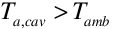 )
)
 (if
(if 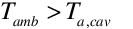 and baffle is vertical)
 is the effectiveness of
the openings that depends on opening geometry and the
orientation with respect to the wind. ASHRAE HoF (2001)
indicates values ranging from 0.25 to 0.6. This value is
available for user input.
is the effectiveness of
the openings that depends on opening geometry and the
orientation with respect to the wind. ASHRAE HoF (2001)
indicates values ranging from 0.25 to 0.6. This value is
available for user input.
 is the discharge
coefficient for the opening and depends on opening geometry.
This value is available for user input.
is the discharge
coefficient for the opening and depends on opening geometry.
This value is available for user input.
Mass continuity arguments lead to modeling the area of the
openings as one half of the total area of the openings, so we
have:
 is the gravitational
constant taken as 9.81 [m/s2].
is the gravitational
constant taken as 9.81 [m/s2].
 is the height from
midpoint of lower opening to the Neutral Pressure Level. This
is value is available for user input.
is the height from
midpoint of lower opening to the Neutral Pressure Level. This
is value is available for user input.
If the cavity is horizontal and  then
then  because this is a stable
situation.
because this is a stable
situation.
Underlying Heat
Transfer Surface[LINK]
The exterior baffle and cavity are applied to the outside
of a heat transfer surface. This surface is modeled using the
usual EnergyPlus methods for handling heat capacity and
transients – typically the CTF method. These native EnergyPlus
heat balance routines are used to calculate . The exterior baffle and cavity
system is coupled to the underlying surface using the SurfaceProperty:OtherSideConditionsModel
mechanism. The exterior naturally vented cavity model provides
values for , ,
, and for use with the heat
balance model calculations for the outside face of the
underlying surface (described elsewhere in this manual).
Solar and Shading
Calculations[LINK]
The exterior vented cavity model uses standard EnergyPlus
surfaces in order to take advantage of the detailed solar and
shading calculations. Solar radiation incident on the surface
includes beam and diffuse radiation, as well as radiation
reflected from the ground and adjacent surfaces. Shading of
the collector by other surfaces, such as nearby buildings or
trees, is also taken into account.
Local Wind Speed
Calculations[LINK]
The outdoor wind speed affects terms used in modeling. The
wind speed in the weather file is assumed to be measured at a
meteorological station located in an open field at a height of
10 m. To adjust for different terrain at the building site and
differences in the height of building surfaces, the local wind
speed is calculated for each surface.
The wind speed is modified from the measured meteorological
wind speed by the equation (ASHRAE 2001):
where z is the height of the centroid of the system,
zmet is the height of the standard meteorological
wind speed measurement, and a and are terrain-dependent
coefficients. is the boundary layer thickness for the given
terrain type. The values of a and are shown in the following
tables:
Terrain-Dependent Coefficients (ASHRAE
2001).
| Terrain |
Description |
Exponent,
a |
Layer Thickness,
(m) |
| 1 |
Flat, open country |
0.14 |
270 |
| 2 |
Rough, wooded country |
0.22 |
370 |
| 3 |
Towns and cities |
0.33 |
460 |
| 4 |
Ocean |
0.10 |
210 |
| 5 |
Urban, industrial,
forest |
0.22 |
370 |
The exterior vented cavity can be defined such that it has
multiple underlying heat transfer surfaces. The centroid
heights for each surface are area-weighted to determine the
average height for use in the local wind calculation.
Convection Coefficients[LINK]
Exterior cavity modeling requires calculating up to three
different coefficients for surface convection heat transfer.
These coefficients are defined in the classic way by:
First, is the convection
coefficient for the baffle surface facing the outdoors. It is
modeled in exactly the same way as elsewhere in EnergyPlus and
will depend on the user setting for Outside Convection
Algorithm – Outside Surface Heat Balance entry elsewhere in
this document.
Second, is the convection
coefficient for baffle surfaces facing the cavity. This
coefficient is applied to both the baffle and the underlying
surface. The convection coefficient is modeled in the same way
used in EnergyPlus to model air gaps in windows. These
correlations vary by Rayleigh number and surface tilt and are
based on the work of various research including Hollands et.
al., Elsherbiny et. al., Wright, and Arnold. The formulations
are documented in ISO (2003) standard 15099. The routines were
adapted from Subroutine NusseltNumber in WindowManager.f90 (by
F. Winkelmann), which itself was derived from Window5
subroutine “nusselt”.
Radiation Coefficients[LINK]
Exterior vented cavity modeling requires calculating up to
four different linearized coefficients for radiation heat
transfer. Whereas radiation calculations usually use
temperature raised to the fourth power, this greatly
complicates solving heat balance equations for a single
temperature. Linearized radiation coefficients have the same
units and are used in the same manner as surface convection
coefficients and introduce very little error for the
temperature levels involved.
The radiation coefficient,
, is used to model thermal radiation between the collector
surface and the outside face of the underlying heat transfer
surface. We assume a view factor of unity. It is calculated
using:
where,
all temperatures are converted to Kelvin,
 is the Stefan-Boltzmann
constant,
is the Stefan-Boltzmann
constant,
 is the longwave thermal
emittance of the baffle, and
is the longwave thermal
emittance of the baffle, and
 is the longwave thermal
emittance of the underlying heat transfer surface.
is the longwave thermal
emittance of the underlying heat transfer surface.
The three other coefficients, ,
, and are used elsewhere in
EnergyPlus for the outside face surface heat balance and are
calculated in the same manner as equation . [This is
accomplished by calling subroutine
InitExteriorConvectionCoeffs in the file
HeatBalanceConvectionCoeffs.f90. ]
ASHRAE HOF 2001. 2001 ASHRAE Fundamentals Handbook.
American Society of Heating Refrigeration and Air-Conditioning
Engineers. Altanta GA.
ISO. 2003. ISO 15099:2003. Thermal performance of windows,
doors, and shading devices – Detailed calculations.
International Organization for Standardization.

Exterior Naturally Vented Cavity[LINK]
The input object “SurfaceProperty:ExteriorNaturalVentedCavity” allows modeling a special case for the outside boundary conditions of heat transfer surfaces with a multi-skin exterior that is opaque. From the thermal envelope’s point of view, the presence of a vented cavity on the outside of the surface modifies the conditions experienced by the underlying heat transfer surfaces. This exterior cavity acts as a radiation and convection baffle situated between the exterior environment and the outside face of the underlying heat transfer surface. The actual outer surface is referred to as the “baffle”. The modeling here assumes that the heat capacity in the outer baffle can be neglected since it is much lower than the underlying mass surface. This object is used with the BuildingSurface:Detailed object where the heat transfer surfaces are referred to as the underlying surfaces. The constructions and materials for the heat transfer surfaces should reflect the construction of just the underlying surface. The SurfaceProperty:ExteriorNaturalVentedCavity object is used to describe the detached layer, or baffle, and the characteristics of the cavity and openings for natural ventilation. This model uses the SurfaceProperty:OtherSideConditionsModel object to pass boundary conditions to the heat transfer modeling for the underlying surfaces.
Baffle Heat Balance[LINK]
The baffle is assumed to be sufficiently thin and high-conductivity so that it can be modeled using a single temperature (for both sides and along its area). This temperature is determined by
formulating a heat balance on a control volume that just
encapsulates the baffle surface. The baffle is assumed to
completely cover the underlying surface such that it is opaque
to shortwave and longwave radiation. This assumption means
that even though the baffle will have some open area for
ventilation, no solar energy passes through these openings.
The heat balance is diagrammed in the following figure.
is determined by
formulating a heat balance on a control volume that just
encapsulates the baffle surface. The baffle is assumed to
completely cover the underlying surface such that it is opaque
to shortwave and longwave radiation. This assumption means
that even though the baffle will have some open area for
ventilation, no solar energy passes through these openings.
The heat balance is diagrammed in the following figure.
The heat balance on the baffle surface’s control volume is:
where:
All terms are positive for net flux to the baffle. Each of these heat balance components is introduced briefly below.
External SW Radiation[LINK]
External LW Radiation[LINK]
External Convection[LINK]
Cavity LW Radiation[LINK]
Cavity Convection[LINK]
Substituting models into (113) and solving for yields the following equation:
where,
Cavity Heat Balance[LINK]
The cavity is the volume of air located between the baffle and the underlying heat transfer surface. The cavity air is modeled as well-mixed. The uniform temperature of the cavity air, , is
determined by formulating a heat balance on a control volume
of air as diagrammed below.
, is
determined by formulating a heat balance on a control volume
of air as diagrammed below.
The heat balance on the cavity air control volume is:
where,
And substituting into yields the following equation:
where,
Modeling natural ventilation air exchanges in a general way is challenging. Simplistic engineering models are used to model resulting from natural
buoyancy and wind forces. Reasoning that the configuration is
similar to single-side natural ventilation, we elect to use
correlations for natural ventilation presented as equations
(29) and (30) in Chapter 26. of ASHRAE HOF (2001).
resulting from natural
buoyancy and wind forces. Reasoning that the configuration is
similar to single-side natural ventilation, we elect to use
correlations for natural ventilation presented as equations
(29) and (30) in Chapter 26. of ASHRAE HOF (2001).
where,
Mass continuity arguments lead to modeling the area of the openings as one half of the total area of the openings, so we have:
If the cavity is horizontal and then
then  because this is a stable
situation.
because this is a stable
situation.
Underlying Heat Transfer Surface[LINK]
The exterior baffle and cavity are applied to the outside of a heat transfer surface. This surface is modeled using the usual EnergyPlus methods for handling heat capacity and transients – typically the CTF method. These native EnergyPlus heat balance routines are used to calculate . The exterior baffle and cavity
system is coupled to the underlying surface using the SurfaceProperty:OtherSideConditionsModel
mechanism. The exterior naturally vented cavity model provides
values for
. The exterior baffle and cavity
system is coupled to the underlying surface using the SurfaceProperty:OtherSideConditionsModel
mechanism. The exterior naturally vented cavity model provides
values for  ,
, ,
,  , and
, and  for use with the heat
balance model calculations for the outside face of the
underlying surface (described elsewhere in this manual).
for use with the heat
balance model calculations for the outside face of the
underlying surface (described elsewhere in this manual).
Solar and Shading Calculations[LINK]
The exterior vented cavity model uses standard EnergyPlus surfaces in order to take advantage of the detailed solar and shading calculations. Solar radiation incident on the surface includes beam and diffuse radiation, as well as radiation reflected from the ground and adjacent surfaces. Shading of the collector by other surfaces, such as nearby buildings or trees, is also taken into account.
Local Wind Speed Calculations[LINK]
The outdoor wind speed affects terms used in modeling. The wind speed in the weather file is assumed to be measured at a meteorological station located in an open field at a height of 10 m. To adjust for different terrain at the building site and differences in the height of building surfaces, the local wind speed is calculated for each surface.
The wind speed is modified from the measured meteorological wind speed by the equation (ASHRAE 2001):
where z is the height of the centroid of the system, zmet is the height of the standard meteorological wind speed measurement, and a and are terrain-dependent coefficients. is the boundary layer thickness for the given terrain type. The values of a and are shown in the following tables:
The exterior vented cavity can be defined such that it has multiple underlying heat transfer surfaces. The centroid heights for each surface are area-weighted to determine the average height for use in the local wind calculation.
Convection Coefficients[LINK]
Exterior cavity modeling requires calculating up to three different coefficients for surface convection heat transfer. These coefficients are defined in the classic way by:
First, is the convection
coefficient for the baffle surface facing the outdoors. It is
modeled in exactly the same way as elsewhere in EnergyPlus and
will depend on the user setting for Outside Convection
Algorithm – Outside Surface Heat Balance entry elsewhere in
this document.
is the convection
coefficient for the baffle surface facing the outdoors. It is
modeled in exactly the same way as elsewhere in EnergyPlus and
will depend on the user setting for Outside Convection
Algorithm – Outside Surface Heat Balance entry elsewhere in
this document.
Second, is the convection
coefficient for baffle surfaces facing the cavity. This
coefficient is applied to both the baffle and the underlying
surface. The convection coefficient is modeled in the same way
used in EnergyPlus to model air gaps in windows. These
correlations vary by Rayleigh number and surface tilt and are
based on the work of various research including Hollands et.
al., Elsherbiny et. al., Wright, and Arnold. The formulations
are documented in ISO (2003) standard 15099. The routines were
adapted from Subroutine NusseltNumber in WindowManager.f90 (by
F. Winkelmann), which itself was derived from Window5
subroutine “nusselt”.
is the convection
coefficient for baffle surfaces facing the cavity. This
coefficient is applied to both the baffle and the underlying
surface. The convection coefficient is modeled in the same way
used in EnergyPlus to model air gaps in windows. These
correlations vary by Rayleigh number and surface tilt and are
based on the work of various research including Hollands et.
al., Elsherbiny et. al., Wright, and Arnold. The formulations
are documented in ISO (2003) standard 15099. The routines were
adapted from Subroutine NusseltNumber in WindowManager.f90 (by
F. Winkelmann), which itself was derived from Window5
subroutine “nusselt”.
Radiation Coefficients[LINK]
Exterior vented cavity modeling requires calculating up to four different linearized coefficients for radiation heat transfer. Whereas radiation calculations usually use temperature raised to the fourth power, this greatly complicates solving heat balance equations for a single temperature. Linearized radiation coefficients have the same units and are used in the same manner as surface convection coefficients and introduce very little error for the temperature levels involved.
The radiation coefficient, , is used to model thermal radiation between the collector
surface and the outside face of the underlying heat transfer
surface. We assume a view factor of unity. It is calculated
using:
, is used to model thermal radiation between the collector
surface and the outside face of the underlying heat transfer
surface. We assume a view factor of unity. It is calculated
using:
where,
all temperatures are converted to Kelvin,
The three other coefficients, ,
,  , and
, and  are used elsewhere in
EnergyPlus for the outside face surface heat balance and are
calculated in the same manner as equation . [This is
accomplished by calling subroutine
InitExteriorConvectionCoeffs in the file
HeatBalanceConvectionCoeffs.f90. ]
are used elsewhere in
EnergyPlus for the outside face surface heat balance and are
calculated in the same manner as equation . [This is
accomplished by calling subroutine
InitExteriorConvectionCoeffs in the file
HeatBalanceConvectionCoeffs.f90. ]
References[LINK]
ASHRAE HOF 2001. 2001 ASHRAE Fundamentals Handbook. American Society of Heating Refrigeration and Air-Conditioning Engineers. Altanta GA.
ISO. 2003. ISO 15099:2003. Thermal performance of windows, doors, and shading devices – Detailed calculations. International Organization for Standardization.
Documentation content copyright © 1996-2026 The Board of Trustees of the University of Illinois and the Regents of the University of California through the Ernest Orlando Lawrence Berkeley National Laboratory. All rights reserved. EnergyPlus is a trademark of the US Department of Energy.
This documentation is made available under the EnergyPlus Open Source License v1.0.