Window Calculation
Module[LINK]
This section describes two potential modeling approaches
for Windows. The first (layer by layer) is implemented. The
second, simple approach, reuses the layer-by-layer approach
but converts an arbitrary window performance into an
equivalent single layer.
The primary Window
calculation is a layer-by-layer approach where windows are
considered to be composed of the following components, only
the first of which, glazing, is required to be present:
- Glazing, which consists of one or more
plane/parallel glass layers. If there are two or more glass
layers, the layers are separated by gaps filled with air or
another gas. The glazing optical and thermal calculations are
based on algorithms from the WINDOW 4 and WINDOW 5 programs
[Arasteh et al., 1989], [Finlayson et al., 1993]. Glazing
layers are described using te input object
WindowMaterial:Glazing.
- Gap, layers filled with air or another
gas that separate glazing layers. Gaps are described using the
input object WindowMaterial:Gas.
- Frame, which surrounds the glazing on
four sides. Frames are described using the input object
WindowProperty:FrameAndDivider.
- Divider, which consists of horizontal
and/or vertical elements that divide the glazing into
individual lites.
- Shading device, which is a separate
layer, such as drapery, roller shade or blind, on the inside
or outside of the glazing, whose purpose is to reduce solar
gain, reduce heat loss (movable insulation) or control
daylight glare. Shading layers are described using
“WindowProperty:ShadingControl” input objects.
In the following, the description of the layer-by-layer
glazing algorithms is based on material from Finlayson et al.,
1993. The frame and divider thermal model, and the shading
device optical and thermal models, are new to EnergyPlus.
A second approch has been developed where windows are
modeled in a simplified approach that requires minimal user
input that is processed to develop and equivalent layer that
then reuses much of the layer-by-model. This “Simple Window
Construction: model is described below.
Optical Properties of
Glazing[LINK]
The solar radiation transmitted by a system of glass layers
and the solar radiation absorbed in each layer depends on the
solar transmittance, reflectance and absorptance properties of
the individual layers. The absorbed solar radiation enters the
glazing heat balance calculation that determines the inside
surface temperature and, therefore, the heat gain to the zone
from the glazing (see “Window Heat Balance Calculation”). The
transmitted solar radiation is absorbed by interior zone
surfaces and, therefore, contributes to the zone heat balance.
In addition, the visible transmittance of the glazing is an
important factor in the calculation of interior daylight
illuminance from the glazing.
Table: Variables in Window
Calculations
Mathematical variable|Description|Units||FORTRAN variable
———————|———–|—–||—————- T|Transmittance|-|- R|Reflectance|-|-
Rf, Rb|Front reflectance, back
reflectance|-|- Ti,j|Transmittance through glass
layers i to j|-|- Tdirgl|Direct
transmittance of glazing|-|- Rfi,j,
Rbi,j|Front reflectance, back
reflectance from glass layers i to j|-|-
Rdirgl,f,
Rdirgl,b|Direct front and back
reflectance of glazing|-|- Afi,
Abi|Front absorptance, back absorptance
of layer i|-|- N|Number of glass layers|-|Nlayer
λ|Wavelength|microns|Wle Es(λ)|Solar spectral
irradiance function|W/m2-micron|E V(λ)|Photopic
response function of the eye|-|y30 φ|Angle of incidence (angle
between surface normal and direction of incident beam
radiation)|Rad|Phi τ|Transmittivity or transmittance|-|tf0
ρ|Reflectivity or reflectance|-|rf0, rb0 α|Spectral absorption
coefficient|m-1|- d|Glass
thickness|M|Material%Thickness n|Index of refraction|-|ngf,
ngb κ|Extinction coefficient|-|- β|Intermediate
variable|-|betaf, betab P, p|A general property, such as
transmittance|-|- τsh|Shade
transmittance|-|Material%Trans ρsh|Shade
reflectance|-|Material%ReflectShade αsh|Shade
absorptance|-|Material%AbsorpSolar
τbl,ρbl,αbl|Blind
transmittance, reflectance, absorptance|-|- Q, G, J|Source,
irradiance and radiosity for blind optical properties
calculation|W/m2|- Fij|View factor
between segments i and j|-|- fswitch|Switching
factor|-|SwitchFac T|Transmittance|-|- R|Reflectance|-|-
Rf, Rb|Front reflectance, back
reflectance|-|- Ti,j|Transmittance through glass
layers i to j|-|- Rfi,j,
Rbi,j|Front reflectance, back
reflectance from glass layers i to j|-|-
Afi, Abi|Front
absorptance, back absorptance of layer i|-|- N|Number of glass
layers|-|Nlayer λ|Wavelength|microns|Wle
Es(λ)|Solar spectral irradiance
function|W/m2-micron|E R(λ)|Photopic response
function of the eye|-|y30 φ’|Relative azimuth angle (angle
between screen surface normal and vertical plane through sun,
Ref. Figure 86)|Rad|SunAzimuthToScreenNormal α’|Relative
altitude angle (angle between screen surface horizontal normal
plane and direction of incident beam radiation, Ref. Figure
86)|Rad|SunAltitudeToScreenNormal
ρsc|Beam-to-diffuse solar reflectance of screen
material|-|Screens%ReflectCylinder γ|Screen material aspect
ratio|-|Screens%ScreenDiameterTo|SpacingRatio Α|Spectral
absorption coefficient|m-1|- D|Glass
thickness|M|Material%Thickness N|Index of refraction|-|ngf,
ngb Κ|Extinction coefficient|-|- Β|Intermediate
variable|-|betaf, betab P, p|A general property, such as
transmittance|-|-
Glass Layer Properties[LINK]
In EnergyPlus, the optical properties of individual glass
layers are given by the following quantities at normal
incidence as a function of wavelength:
Transmittance, T
Front reflectance, Rf
Back reflectance, Rb
Here “front” refers to radiation incident on the side of
the glass closest to the outside environment, and “back”
refers to radiant incident on the side of the glass closest to
the inside environment. For glazing in exterior walls, “front”
is therefore the side closest to the outside air and “back” is
the side closest to the zone air. For glazing in interior
(i.e., interzone) walls, “back” is the side closest to the
zone in which the wall is defined in and “front” is the side
closest to the adjacent zone.
Glass Optical
Properties Conversion[LINK]
Conversion
from Glass Optical Properties Specified as Index of Refraction
and Transmittance at Normal Incidence[LINK]
The optical properties of uncoated glass are sometimes
specified by index of refraction, n,and
transmittance at normal incidence, T.
The following equations show how to convert from this set
of values to the transmittance and reflectance values required
by Material:WindowGlass. These equations apply only to
uncoated glass, and can be used to convert either
spectral-average solar properties or spectral-average visible
properties (in general, n and T are
different for the solar and visible). Note that since the
glass is uncoated, the front and back reflectances are the
same and equal to the R that is solved for in the
following equations.
Given n and T, find R:
Example:
T = 0.86156
n = 1.526
Simple Window Model[LINK]
EnergyPlus includes an alternate model that allows users to
enter in simplified window performance indices. This model is
accessed through the WindowMaterial:SimpleGlazingSystem
input object and converts the simple indices into an
equivalent single layer window. (In addition a special model
is used to determine the angular properties of the system –
described below). Once the model generates the properties for
the layer, the program reuses the bulk of the layer-by-layer
model for subsequent calculations. The properties of the
equivalent layer are determined using the step by step method
outlined by Arasteh, Kohler, and Griffith (2009). The core
equations are documented here. The reference contains
additional information.
The simplified window model accepts U and SHGC indices and
is useful for several reasons:
- Sometimes, the only thing that is known about the window
are its U and SHGC;
- Codes, standards, and voluntary programs are developed in
these terms;
- A single-layer calculation is faster than multi-layer
calculations.
Note: This use of U and SHGC to describe the thermal
properties of windows is only appropriate for specular
glazings.
While it is important to include the ability to model
windows with only U-value and SHGC, we note that any method to
use U and SHGC alone in building simulation software will
inherently be approximate. This is due primarily to the
following factors:
SHGC combines directly transmitted solar radiation and
radiation absorbed by the glass which flows inward. These have
different implications for space heating/cooling. Different
windows with the same SHGC often have different ratios of
transmitted to absorbed solar radiation.
SHGC is determined at normal incidence; angular properties
of glazings vary with number of layers, tints, coatings. So
products which have the same SHGC, can have different angular
properties.
Window
U-factors vary with temperatures.
Thus, for modeling specific windows, we recommend using
more detailed data than just the U and SHGC, if at all
possible.
The simplified window model determines the properties of an
equivalent layer in the following steps.
Step 1.
Determine glass-to-glass Resistance.[LINK]
Window
U-values include interior and exterior surface heat transfer
coefficients. The resistance of the bare window product, or
glass-to-glass resistance is augmented by these film
coefficients so that,
Where,
 is the resistance of the
interior film coefficient under standard winter conditions in
units of m2·K/W,
is the resistance of the
interior film coefficient under standard winter conditions in
units of m2·K/W,
 is the resistance of the
exterior film coefficient under standard winter conditions in
units of m2·K/W, and
is the resistance of the
exterior film coefficient under standard winter conditions in
units of m2·K/W, and
 is the resisance of the
bare window under winter conditions (without the film
coefficients) in units of m2·K/W.
is the resisance of the
bare window under winter conditions (without the film
coefficients) in units of m2·K/W.
The values for  and
and  depend on U and are calculated
using the following correlations.
depend on U and are calculated
using the following correlations.
So that the glass-to-glass resistance is calculated
using,
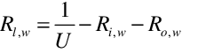 .
.
Because the window model in EnergyPlus is for flat
geometries, the models are not necessarily applicable to
low-performance projecting products, such as skylights with
unisulated curbs. The model cannot support glazing systems
with a U higher than 7.0 because the thermal resistance of the
film coefficients alone can provide this level of performance
and none of the various resistances can be negative.
Step 2. Determine
Layer Thickness.[LINK]
The thickness of the equivalent layer in units of meters is
calculated using,
Step 3.
Determine Layer Thermal Conductivity[LINK]
The effective thermal conductivity,  , of the equivalent layer is
calculated using,
, of the equivalent layer is
calculated using,
Step 4.
Determine Layer Solar Transmittance[LINK]
The layer’s solar transmittance at normal incidence,  , is calculated using correlations
that are a function of SHGC and U-Factor.
, is calculated using correlations
that are a function of SHGC and U-Factor.
And for U-values between 3.4 and 4.5, the value for  is interpolated using results of
the equations for both ranges.
is interpolated using results of
the equations for both ranges.
Step 5.
Determine Layer Solar Reflectance[LINK]
The layer’s solar reflectance is calculated by first
determining the inward flowing fraction which requires values
for the resistance of the inside and outside film coefficients
under summer conditions,  and
and
 respectively. The
correlations are
respectively. The
correlations are



And for U-values between 3.4 and 4.5, the values are
interpolated using results from both sets of equations.
The inward flowing fraction, 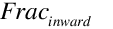 , is then calculated using
The the solar reflectances of the front face,  , and back face,
  , are calculated using,
 .
.
The thermal absorptance, or emittance, is take as 0.84 for
both the front and back and the longwave transmittance is
0.0.
Step 6.
Determine Layer Visible Properties[LINK]
The user has the option of entering a value for visible
transmittance as one of the simple performance indices. If the
user does not enter a value, then the visible properties are
the same as the solar properties. If the user does enter a
value then layer’s visible transmittance at normal incidence,
 ,is set to that value. The
visible light reflectance for the back surface is calculated
using,
,is set to that value. The
visible light reflectance for the back surface is calculated
using,
The visible light reflectance for the front surface is
calculated using,
The angular properties of windows are important because
during energy modeling, the solar incidence angles are usually
fairly high. Angles of incidence are defined as angles from
the normal direction extending out from the window. The simple
glazing system model includes a range of correlations that are
selected based on the values for U and SHGC. These were chosen
to match the types of windows likely to have such performance
levels. The matrix of possible combinations of U and SHGC
values have been mapped to set of 28 bins shown in the
following figure.
There are ten different correlations, A thru J, for both
transmission and reflectance. The correlations are used in
various weighting and interpolation schemes according the
figure above. The correlations are normalized against the
performance at normal incidence. EnergyPlus uses these
correlations to store the glazing system’s angular performance
at 10 degree increments and interpolates between them during
simulations. The model equations use the cosine of the
incidence angle,  , as the
independent variable. The correlations have the form:
, as the
independent variable. The correlations have the form:
The coefficient values for a, b, c, d, and e are listed in
the following tables for each of the curves.
Application Issues[LINK]
EnergyPlus’s normal process of running the detailed
layer-by-layer model, with the equivalent layer produced by
this model, creates reports (sent to the EIO file) of the
overall performance indices and the properties of the
equivalent layer. Both of these raise issues that may be
confusing.
The simplified window model does not reuse all aspects of
the detailed layer-by-layer model, in that the angular solar
transmission properties use a different model when the simple
window model is in effect. If the user takes the material
properties of an equivalent glazing layer from the simple
window model and then re-enters them into just the detailed
model, then the performance will not be the same because of
the angular transmission model will have changed. It is not
proper use of the model to re-enter the equivalent layer’s
properties and expect the exact level of performance.
There may not be exact agreement between the performance
indices echoed out and those input in the model. This is
expected with the model and the result of a number of factors.
For example, although input is allowed to go up to U-7
W/m2∙K, the actual outcome is limited to no higher
than about 5.8W/m2∙K. This is because the thermal
resistance to heat transfer at the surfaces is already enough
resistance to provide an upper limit to the conductance of a
planar surface. Sometimes there is conflict between the SHGC
and the U that are not physical and compromises need to be
made. In general, the simple window model is intended to
generate a physically-reasonable glazing that approximates the
input entered as well as possible. But the model is not always
be able to do exactly what is specified when the
specifications are not physical.
Arasteh, D., J.C. Kohler, B. Griffith, Modeling Windows in
EnergyPlus with Simple Performance Indices. Lawrence Berkeley
National Laboratory. In Draft. Available at
http://windows.lbl.gov/win_prop/ModelingWindowsInEnergyPlusWithSimplePerformanceIndices.pdf
Glazing System
Properties[LINK]
The optical properties of a glazing system consisting of
N glass layers separated by nonabsorbing gas layers
(Figure 76. Schematic of transmission, reflection and
absorption of solar radiation within a multi-layer glazing
system.) are determined by solving the following recursion
relations for Ti,j , the transmittance
through layers i to j;
Rfi,j~~and
Rbi,j, the front and back
reflectance, respectively, from layers i to
j; and Aj , the absorption in
layer j. Here layer 1 is the outermost layer and
layer N is the innermost layer. These relations
account for multiple internal reflections within the glazing
system. Each of the variables is a function of wavelength.
In Eq. Ti,j = 1 and
Ri,j = 0 if i<0 or
j>N.
As an example, for double glazing (N=2) these
equations reduce to
If the above transmittance and reflectance properties are
input as a function of wavelength, EnergyPlus calculates
“spectral average” values of the above glazing system
properties by integrating over wavelength:
The spectral-average solar property is
The spectral-average visible property is
where 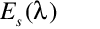 is the solar
spectral irradiance function and
is the solar
spectral irradiance function and  is the photopic response function
of the eye. The default functions are shown in Table 27 and
Table 28. They can be overwritten by user defined solar and/or
visible spectrum using the objects Site:SolarAndVisibleSpectrum
and Site:SpectrumData.
They are expressed as a set of values followed by the
corresponding wavelengths for values.
is the photopic response function
of the eye. The default functions are shown in Table 27 and
Table 28. They can be overwritten by user defined solar and/or
visible spectrum using the objects Site:SolarAndVisibleSpectrum
and Site:SpectrumData.
They are expressed as a set of values followed by the
corresponding wavelengths for values.
If a glazing layer has optical properties that are roughly
constant with wavelength, the wavelength-dependent values of
Ti,i ,
Rfi,i~~and
Rbi,i in Eqs. to can be
replaced with constant values for that layer.
Table 27: Solar spectral irradiance function.
Air
mass 1.5 terrestrial solar global spectral irradiance values
(W/m2-micron) on a 37o tilted surface.
Corresponds to wavelengths in following data block. Based on
ISO 9845-1 and ASTM E 892; derived from Optics5 data file
ISO-9845GlobalNorm.std, 10-14-99.[LINK]
0.0, 9.5, 42.3, 107.8, 181.0, 246.0, 395.3, 390.1, 435.3, 438.9, | 483.7, 520.3, 666.2, 712.5, 720.7,1013.1,1158.2,1184.0,1071.9,1302.0, | 1526.0,1599.6,1581.0,1628.3,1539.2,1548.7,1586.5,1484.9,1572.4,1550.7, | 1561.5,1501.5,1395.5,1485.3,1434.1,1419.9,1392.3,1130.0,1316.7,1010.3, | 1043.2,1211.2,1193.9,1175.5, 643.1,1030.7,1131.1,1081.6, 849.2, 785.0, | 916.4, 959.9, 978.9, 933.2, 748.5, 667.5, 690.3, 403.6, 258.3, 313.6, | 526.8, 646.4, 746.8, 690.5, 637.5, 412.6, 108.9, 189.1, 132.2, 339.0, | 460.0, 423.6, 480.5, 413.1, 250.2, 32.5, 1.6, 55.7, 105.1, 105.5, | 182.1, 262.2, 274.2, 275.0, 244.6, 247.4, 228.7, 244.5, 234.8, 220.5, | 171.5, 30.7, 2.0, 1.2, 21.2, 91.1, 26.8, 99.5, 60.4, 89.1, | 82.2, 71.5, 70.2, 62.0, 21.2, 18.5, 3.2
Wavelengths (microns) corresponding to above data block
0.3000,0.3050,0.3100,0.3150,0.3200,0.3250,0.3300,0.3350,0.3400,0.3450,
|
0.3500,0.3600,0.3700,0.3800,0.3900,0.4000,0.4100,0.4200,0.4300,0.4400,
|
0.4500,0.4600,0.4700,0.4800,0.4900,0.5000,0.5100,0.5200,0.5300,0.5400,
|
0.5500,0.5700,0.5900,0.6100,0.6300,0.6500,0.6700,0.6900,0.7100,0.7180,
|
0.7244,0.7400,0.7525,0.7575,0.7625,0.7675,0.7800,0.8000,0.8160,0.8237,
|
0.8315,0.8400,0.8600,0.8800,0.9050,0.9150,0.9250,0.9300,0.9370,0.9480,
|
0.9650,0.9800,0.9935,1.0400,1.0700,1.1000,1.1200,1.1300,1.1370,1.1610,
|
1.1800,1.2000,1.2350,1.2900,1.3200,1.3500,1.3950,1.4425,1.4625,1.4770,
|
1.4970,1.5200,1.5390,1.5580,1.5780,1.5920,1.6100,1.6300,1.6460,1.6780,
|
1.7400,1.8000,1.8600,1.9200,1.9600,1.9850,2.0050,2.0350,2.0650,2.1000,
| 2.1480,2.1980,2.2700,2.3600,2.4500,2.4940,2.5370
Table 28: Photopic response function.
Photopic
response function values corresponding to wavelengths in
following data block. Based on CIE 1931 observer; ISO/CIE
10527, CIE Standard Calorimetric Observers; derived from
Optics5 data file “CIE 1931 Color Match from E308.txt”, which
is the same as WINDOW4 file Cie31t.dat.[LINK]
0.0000,0.0001,0.0001,0.0002,0.0004,0.0006,0.0012,0.0022,0.0040,0.0073, | 0.0116,0.0168,0.0230,0.0298,0.0380,0.0480,0.0600,0.0739,0.0910,0.1126, | 0.1390,0.1693,0.2080,0.2586,0.3230,0.4073,0.5030,0.6082,0.7100,0.7932, | 0.8620,0.9149,0.9540,0.9803,0.9950,1.0000,0.9950,0.9786,0.9520,0.9154, | 0.8700,0.8163,0.7570,0.6949,0.6310,0.5668,0.5030,0.4412,0.3810,0.3210, | 0.2650,0.2170,0.1750,0.1382,0.1070,0.0816,0.0610,0.0446,0.0320,0.0232, | 0.0170,0.0119,0.0082,0.0158,0.0041,0.0029,0.0021,0.0015,0.0010,0.0007, | 0.0005,0.0004,0.0002,0.0002,0.0001,0.0001,0.0001,0.0000,0.0000,0.0000, | 0.0000 /
Wavelengths (microns) corresponding to above data block
.380,.385,.390,.395,.400,.405,.410,.415,.420,.425,|
.430,.435,.440,.445,.450,.455,.460,.465,.470,.475,|
.480,.485,.490,.495,.500,.505,.510,.515,.520,.525,|
.530,.535,.540,.545,.550,.555,.560,.565,.570,.575,|
.580,.585,.590,.595,.600,.605,.610,.615,.620,.625, |
.630,.635,.640,.645,.650,.655,.660,.665,.670,.675,|
.680,.685,.690,.695,.700,.705,.710,.715,.720,.725,|
.730,.735,.740,.745,.750,.755,.760,.765,.770,.775, | .780
Calculation of
Angular Properties[LINK]
Calculation of optical properties is divided into two
categories: uncoated glass and coated glass.
Angular
Properties for Uncoated Glass[LINK]
The following discussion assumes that optical quantities
such as transmissivity, reflectvity, absorptivity, and index
of refraction are a function of wavelength, λ. If there are no
spectral data the angular dependence is calculated based on
the single values for transmittance and reflectance in the
visible and solar range. In the visible range an average
wavelength of 0.575 microns is used in the calculations. In
the solar range an average wavelength of 0.898 microns is
used.
The spectral data include the transmittance, T,
and the reflectance, R. For uncoated glass the
reflectance is the same for the front and back surfaces. For
angle of incidence,  , the
transmittance and reflectance are related to the
transmissivity, τ, and reflectivity, ρ, by the following
relationships:
, the
transmittance and reflectance are related to the
transmissivity, τ, and reflectivity, ρ, by the following
relationships:
The spectral reflectivity is calculated from Fresnel’s
equation assuming unpolarized incident radiation:
The spectral transmittivity is given by
The spectral absorption coefficient is defined as
where κ is the dimensionless spectrally-dependent
extinction coefficient and λ is the wavelength expressed in
the same units as the sample thickness.
Solving Eq. at normal incidence gives
Evaluating Eq. at normal incidence gives the following
expression for κ
Eliminating the exponential in Eqs. and gives the
reflectivity at normal incidence:
where
The value for the reflectivity, ρ(0), from Eq. is
substituted into Eqs. and . The result from Eq. is used to
calculate the absorption coefficient in Eq. . The index of
refraction is used to calculate the reflectivity in Eq. which
is then used to calculate the transmittivity in Eq. . The
reflectivity, transmissivity and absorption coefficient are
then substituted into Eqs. and to obtain the angular values of
the reflectance and transmittance.
Angular
Properties for Coated Glass[LINK]
A regression fit is used to calculate the angular
properties of coated glass from properties at normal
incidence. If the transmittance of the coated glass is >
0.645, the angular dependence of uncoated clear glass is used.
If the transmittance of the coated glass is ≤ 0.645, the
angular dependence of uncoated bronze glass is used. The
values for the angular functions for the transmittance and
reflectance of both clear glass 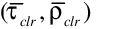 and bronze glass
 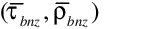 are determined from a fourth-order
polynomial regression:
are determined from a fourth-order
polynomial regression:
and
The polynomial coefficients are given in Table 29.
Table 29: Polynomial coefficients used to determine angular
properties of coated glass.
| 0 |
1 |
2 |
3 |
4 |
 |
-0.0015 |
3.355 |
-3.840 |
1.460 |
 |
0.999 |
-0.563 |
2.043 |
-2.532 |
 |
-0.002 |
2.813 |
-2.341 |
-0.05725 |
 |
0.997 |
-1.868 |
6.513 |
-7.862 |
These factors are used as follows to calculate the angular
transmittance and reflectance:
For T(0) > 0.645:
For T(0) ≤ 0.645:
Angular
Properties for Simple Glazing Systems[LINK]
When the glazing system is modeled using the simplified
method, an alternate method is used to determine the angular
properties. The equation for solar transmittance as a function
of incidence angle,  , is,
, is,
where,
 is the normal incidence
solar transmittance,
is the normal incidence
solar transmittance,  .
.
The equation for solar reflectance as a function of
incidence angle,  , is,
, is,
where,
Calculation of
Hemispherical Values[LINK]
The hemispherical value of a property is determined from
the following integral:
The integral is evaluated by Simpson’s rule for property
values at angles of incidence from 0 to 90 degrees in
10-degree increments.
Optical
Properties of Window Shading Devices[LINK]
Shading devices affect the system transmittance and glass
layer absorptance for short-wave radiation and for long-wave
(thermal) radiation. The effect depends on the shade position
(interior, exterior or between-glass), its transmittance, and
the amount of inter-reflection between the shading device and
the glazing. Also of interest is the amount of radiation
absorbed by the shading device.
In EnergyPlus, shading devices are divided into four
categories, “shades,” “blinds,” “screens,” and “switchable
glazing.” “Shades” are assumed to be perfect diffusers. This
means that direct radiation incident on the shade is reflected
and transmitted as hemispherically uniform diffuse radiation:
there is no direct component of transmitted radiation. It is
also assumed that the transmittance, τsh,
reflectance, ρsh, and absorptance,
αsh, are the same for the front and back
of the shade and are independent of angle of incidence. Many
types of drapery and pull-down roller devices are close to
being perfect diffusers and can be categorized as
“shades.”
“Blinds” in EnergyPlus are slat-type devices such as
venetian blinds. Unlike shades, the optical properties of
blinds are strongly dependent on angle of incidence. Also,
depending on slat angle and the profile angle of incident
direct radiation, some of the direct radiation may pass
between the slats, giving a direct component of transmitted
radiation.
“Screens” are debris or insect protection devices made up
of metallic or non-metallic materials. Screens may also be
used as shading devices for large glazing areas where
excessive solar gain is an issue. The EnergyPlus window screen
model assumes the screen is composed of intersecting
orthogonally-crossed cylinders, with the surface of the
cylinders assumed to be diffusely reflecting. Screens may only
be used on the exterior surface of a window construction. As
with blinds, the optical properties affecting the direct
component of transmitted radiation are dependent on the angle
of incident direct radiation.
With “Switchable glazing,” shading is achieved making the
glazing more absorbing or more reflecting, usually by an
electrical or chemical mechanism. An example is electrochromic
glazing where the application of an electrical voltage or
current causes the glazing to switch from light to dark.
Shades and blinds can be either fixed or moveable. If
moveable, they can be deployed according to a schedule or
according to a trigger variable, such as solar radiation
incident on the window. Screens can be either fixed or
moveable according to a schedule.
Shade/Glazing
System Properties for Short-Wave Radiation[LINK]
Short-wave radiation includes
Beam solar radiation from the sun and diffuse solar
radiation from the sky and ground incident on the outside of
the window,
Beam and/or diffuse radiation reflected from exterior
obstructions or the building itself,
Solar radiation reflected from the inside zone surfaces and
incident as diffuse radiation on the inside of the window,
Beam solar radiation from one exterior window incident on
the inside of another window in the same zone, and
Short-wave radiation from electric lights incident as
diffuse radiation on the inside of the window.
Exterior Shade
For an exterior shade we have the following expressions for
the system transmittance, the effective system glass layer
absorptance, and the system shade absorptance, taking
inter-reflection between shade and glazing into account. Here,
“system” refers to the combination of glazing and shade. The
system properties are given in terms of the isolated shade
properties (i.e., shade properties in the absence of the
glazing) and the isolated glazing properties (i.e., glazing
properties in the absence of the shade).
Interior Shade
The system properties when an interior shade is in place
are the following.
Long-Wave
Radiation Properties of Window Shades[LINK]
Long-wave radiation includes
Thermal radiation from the sky, ground and exterior
obstructions incident on the outside of the window,
Thermal radiation from other room surfaces incident on the
inside of the window, and
Thermal radiation from internal sources, such as equipment
and electric lights, incident on the inside of the window.
The program calculates how much long-wave radiation is
absorbed by the shade and by the adjacent glass surface. The
system emissivity (thermal absorptance) for an interior or
exterior shade, taking into account reflection of long-wave
radiation between the glass and shade, is given by
where  is the long-wave
reflectance of the outermost glass surface for an exterior
shade or the innermost glass surface for an interior shade,
and it is assumed that the long-wave transmittance of the
glass is zero.
is the long-wave
reflectance of the outermost glass surface for an exterior
shade or the innermost glass surface for an interior shade,
and it is assumed that the long-wave transmittance of the
glass is zero.
The innermost (for interior shade) or outermost (for
exterior shade) glass surface emissivity when the shade is
present is
Switchable Glazing[LINK]
For switchable glazing, such as electrochromics, the solar
and visible optical properties of the glazing can switch from
a light state to a dark state. The switching factor,
fswitch, determines what state the glazing
is in. An optical property, p, such as transmittance
or glass layer absorptance, for this state is given by
where
plight is the property value for the
unswitched, or light state, and pdark is
the property value for the fully switched, or dark state.
The value of the switching factor in a particular time step
depends on what type of switching control has been specified:
“schedule,” “trigger,” or “daylighting.” If “schedule,”
fswitch = schedule value, which can be 0
or 1.
Thermochromic Windows[LINK]
Thermochromic (TC) materials have active, reversible
optical properties that vary with temperature. Thermochromic
windows are adaptive window systems for incorporation into
building envelopes. Thermochromic windows respond by absorbing
sunlight and turning the sunlight energy into heat. As the
thermochromic film warms it changes its light transmission
level from less absorbing to more absorbing. The more sunlight
it absorbs the lower the light level going through it. Figure
77 shows the variations of window properties with the
temperature of the thermochromic glazing layer. By using the
suns own energy the window adapts based solely on the
directness and amount of sunlight. Thermochromic materials
will normally reduce optical transparency by absorption and/or
reflection, and are specular (maintaining vision).
On cloudy days the window is at full transmission and
letting in diffuse daylighting. On sunny days the window
maximizes diffuse daylighting and tints based on the angle of
the sun relative to the window. For a south facing window
(northern hemisphere) the daylight early and late in the day
is maximized and the direct sun at mid day is minimized.
The active thermochromic material can be embodied within a
laminate layer or a surface film. The overall optical state of
the window at a given time is a function primarily of
thermochromic material properties
solar energy incident on the window
construction of the window system that incorporates the
thermochromic layer
environmental conditions (interior, exterior, air
temperature, wind, etc).
The tinted film, in combination with a heat reflecting,
low-e layer allows the window to reject most of the absorbed
radiation thus reducing undesirable heat load in a building.
In the absence of direct sunlight the window cools and clears
and again allows lower intensity diffuse radiation into a
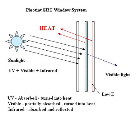
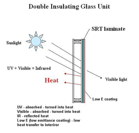
building. TC windows can be designed in several ways (Figure
78), with the most common being a triple pane windows with the
TC glass layer in the middle a double pane windows with the TC
layer on the inner surface of the outer pane or for sloped
glazing a double pane with the laminate layer on the inner
pane with a low-e layer toward the interior. The TC glass
layer has variable optical properties depending on its
temperature, with a lower temperature at which the optical
change is initiated, and an upper temperature at which a
minimum transmittance is reached. TC windows act as passive
solar shading devices without the need for sensors, controls
and power supplies but their optical performance is dependent
on varying solar and other environmental conditions at the
location of the window.
EnergyPlus describes a thermochromic window with a Construction
object which references a special layer defined with a WindowMaterial:GlazingGroup:Thermochromic
object. The WindowMaterial:GlazingGroup:Thermochromic
object further references a series of WindowMaterial:Glazing
objects corresponding to each specification temperature of the
TC layer. During EnergyPlus run time, a series of TC windows
corresponding to each specification temperature is created
once. At the beginning of a particular time step calculations,
the temperature of the TC glass layer from the previous time
step is used to look up the most closed specification
temperature whose corresponding TC window construction will be
used for the current time step calculations. The current time
step calculated temperature of the TC glass layer can be
different from the previous time step, but no iterations are
done in the current time step for the new TC glass layer
temperature. This is an approximation that considers the
reaction time of the TC glass layer can be close to EnergyPlus
simulation time step say 10 to 15 minutes.
Window
blinds in EnergyPlus are defined as a series of equidistant
slats that are oriented horizontally or vertically. All of the
slats are assumed to have the same optical properties. The
overall optical properties of the blind are determined by the
slat geometry (width, separation and angle) and the slat
optical properties (front-side and back-side transmittance and
reflectance). Blind properties for direct radiation are also
sensitive to the “profile angle,” which is the angle of
incidence in a plane that is perpendicular to the window plane
and to the direction of the slats. The blind optical model in
EnergyPlus is based on Simmler, Fischer and Winkelmann, 1996;
however, that document has numerous typographical errors and
should be used with caution.
The following assumptions are made in calculating the blind
optical properties:
- The slats are flat.
- The spectral dependence of inter-reflections between slats
and glazing is ignored; spectral-average slat optical
properties are used.
- The slats are perfect diffusers. They have a perfectly
matte finish so that reflection from a slat is isotropic
(hemispherically uniform) and independent of angle of
incidence, i.e., the reflection has no specular component.
This also means that absorption by the slats is
hemispherically uniform with no incidence angle dependence. If
the transmittance of a slat is non-zero, the transmitted
radiation is isotropic and the transmittance is independent of
angle of incidence.
- Inter-reflection between the blind and wall elements near
the periphery of the blind is ignored.
- If the slats have holes through which support strings
pass, the holes and strings are ignored. Any other structures
that support or move the slats are ignored.
Slat Optical Properties[LINK]
The slat optical properties used by EnergyPlus are shown in
the following table.
Table: Slat Optical Properties
 ||Direct-to-diffuse
transmittance (same for front and back of slat)
————————||—————————————————————–
||Direct-to-diffuse
transmittance (same for front and back of slat)
————————||—————————————————————–  ||Diffuse-to-diffuse transmittance
(same for front and back of slat)
||Diffuse-to-diffuse transmittance
(same for front and back of slat) 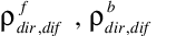 ||Front and back direct-to-diffuse
reflectance
||Front and back direct-to-diffuse
reflectance 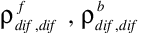 |Front and back
diffuse-to-diffuse reflectance
|Front and back
diffuse-to-diffuse reflectance
It is assumed that there is no direct-to-direct
transmission or reflection, so that 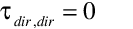 ,
, 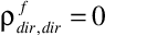 , and
, and 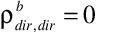 . It is further assumed
that the slats are perfect diffusers, so that
. It is further assumed
that the slats are perfect diffusers, so that  ,
,  and
and  are independent of angle
of incidence. Until the EnergyPlus model is improved to take
into account the angle-of-incidence dependence of slat
transmission and reflection, it is assumed that
are independent of angle
of incidence. Until the EnergyPlus model is improved to take
into account the angle-of-incidence dependence of slat
transmission and reflection, it is assumed that  =
=  ,
,  =
= , and
, and  =
= .
.
Direct Transmittance of
Blind[LINK]
The direct-to-direct and direct-to-diffuse transmittance of
a blind is calculated using the slat geometry shown in Figure
79 (a), which shows the side view of one of the cells of the
blind. For the case shown, each slat is divided into two
segments, so that the cell is bounded by a total of six
segments, denoted by s1 through
s6 (note in the following that
sirefers to both segment i and
the length of segment i).The lengths of
s1 and s2 are equal to
the slat separation, h, which is the distance between
adjacent slat faces. s3 and
s4 are the segments illuminated by direct
radiation. In the case shown in Figure 79 (a) the cell
receives radiation by reflection of the direct radiation
incident on s4 and, if the slats have
non-zero transmittance, by transmission through
s3, which is illuminated from above.
The goal of the blind direct transmission calculation is to
determine the direct and diffuse radiation leaving the cell
through s2 for unit direct radiation
entering the cell through s1.

Direct-to-Direct
Blind Transmittance[LINK]
Figure 79 (b) shows the case where some of the direct
radiation passes through the cell without hitting the slats.
From the geometry in this figure we see that
where
Note that we are assuming that the slat thickness is zero.
A correction for non-zero slat thickness is described
later.
Direct-to-Diffuse
Blind Transmittance, Reflectance and Absorptance[LINK]
The direct-to-diffuse and transmittance and reflectance of
the blind are calculated using a radiosity method that
involves the following three vector quantities:
Ji = the radiosity of segment
si, i.e., the total radiant flux into the
cell from si
Gi = the irradiance on the cell side of
si
Qi = the source flux from the cell side
of si
Based on these definitions we have the following equations
that relate J, G and Q for the
different segments:
In addition we have the following equation relating
G and J:
where  is the view factor
between
is the view factor
between  and
and  , i.e., is the fraction of radiation
leaving that is intercepted
by .
, i.e., is the fraction of radiation
leaving that is intercepted
by .
Using 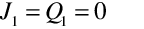 and
and  and combining the above equations
gives the following equation set relating J and
Q:
and combining the above equations
gives the following equation set relating J and
Q:
This can be written in the form
where X is a 4x4 matrix and
We then obtain  from
from
The view factors,  , are
obtained as follows. The cell we are dealing with is a convex
polygon with n sides. In such a polygon the view
factors must satisfy the following constraints:
, are
obtained as follows. The cell we are dealing with is a convex
polygon with n sides. In such a polygon the view
factors must satisfy the following constraints:
These constraints lead to simple equations for the view
factors for n = 3 and 4. For n = 3, we have
the following geometry and view factor expression:
For n = 4 we have:
Applying these to the slat cell shown in Figure 80 we have
the following:
The sources for the direct-to-diffuse transmittance
calculation are:
For unit incident direct flux, the front direct-to-diffuse
transmittance and reflectance of the blind are:
where
and  to
to  are given by Eq. .
The front direct absorptance of the blind is then
The direct-to-diffuse calculations are performed separately
for solar and visible slat properties to get the corresponding
solar and visible blind properties.
Dependence on Profile
Angle[LINK]
The direct-to-direct and direct-to-diffuse blind properties
are calculated for direct radiation profile angles (see Figure
79) ranging from –90O to +90O in
5O increments. (The “profile angle” is the angle of
incidence in a plane that is perpendicular to the window
and perpendicular to the slat direction.) In the time
step loop the blind properties for a particular profile angle
are obtained by interpolation.
Dependence on Slat
Angle[LINK]
All blind properties are calculated for slat angles ranging
from –90O to +90O in 10O
increments. In the time-step loop the slat angle is determined
by the slat-angle control mechanism and then the blind
properties at that slat angle are determined by interpolation.
Three slat-angle controls are available: (1) slat angle is
adjusted to just block beam solar incident on the window; (2)
slat angle is determined by a schedule; and (3) slat angle is
fixed.
Diffuse-to-Diffuse
Transmittance and Reflectance of Blind[LINK]
To calculate the diffuse-to-diffuse properties, assuming
uniformly distributed incident diffuse radiation, each slat
bounding the cell is divided into two segments of equal length
(Figure 81), i.e.,  and
and  . For front-side properties we
have a unit source,
. For front-side properties we
have a unit source,  . All
the other
. All
the other  are zero. Using
this source value, we apply the methodology described above to
obtain G2 and G1. We
then have
are zero. Using
this source value, we apply the methodology described above to
obtain G2 and G1. We
then have
The back-side properties are calculated in a similar way by
setting Q2 = 1 with the other equal to zero.
The diffuse-to-diffuse calculations are performed
separately for solar, visible and IR slat properties to get
the corresponding solar, visible and IR blind properties.
Blind
properties for sky and ground diffuse radiation[LINK]
For horizontal slats on a vertical window (the most common
configuration) the blind diffuse-to-diffuse properties will be
sensitve to whether the radiation is incident upward from the
ground or downward from the sky (Figure 82). For this reason
we also calculate the following solar properties for a blind
consisting of horizontal slats in a vertical plane:
 front transmittance for
ground diffuse solar
front transmittance for
ground diffuse solar
 front transmittance for
sky diffuse solar
front transmittance for
sky diffuse solar
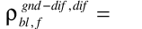 front reflectance for
ground diffuse solar
front reflectance for
ground diffuse solar
 front reflectance for sky
diffuse solar
front reflectance for sky
diffuse solar
 front absorptance for
ground diffuse solar
front absorptance for
ground diffuse solar
 front absorptance for sky
diffuse solar
front absorptance for sky
diffuse solar
These are obtained by integrating over sky and ground
elements, as shown in Figure 82, treating each element as a
source of direct radiation of irradiance  incident on the blind at profile
angle
incident on the blind at profile
angle  . This gives:
We assume that the sky radiance is uniform. This means that
 is independent of
  , giving:
The corresponding ground diffuse quantities are obtained by
integrating  from
from  to 0.
to 0.
An improvement to this calculation would be to allow the
sky radiance distribution to be non-uniform, i.e., to depend
on sun position and sky conditions, as is done in the detailed
daylighting calculation (see “Sky Luminance Distributions”
under “Daylight Factor Calculation”).
Correction
Factor for Slat Thickness[LINK]
A correction has to be made to the blind transmittance,
reflectance and absorptance properties to account for the
amount of radiation incident on a blind that is reflected and
absorbed by the slat edges (the slats are assumed to be opaque
to radiation striking the slat edges). This is illustrated in
Figure 83 for the case of direct radiation incident on the
blind. The slat cross-section is assumed to be rectangular.
The quantity of interest is the fraction,
fedge, of direct radiation incident on the
blind that strikes the slat edges. Based on the geometry shown
in Figure 83 we see that
The edge correction factor for diffuse incident radiation
is calculated by averaging this value of
fedge over profile angles,
φs, from –90O to
+90O.
As an example of how the edge correction factor is applied,
the following two equations show how blind front diffuse
transmittance and reflectance calculated assuming zero slat
thickness are modified by the edge correction factor. It is
assumed that the edge transmittance is zero and that the edge
reflectance is the same as the slat front reflectance,
ρf.
Comparison
with ISO 15099 Calculation of Blind Optical Properties[LINK]
Table 31 compares EnergyPlus and ISO 15099 [2001]
calculations of blind optical properties for a variety of
profile angles, slat angles and slat optical properties. The
ISO 15099 calculation method is similar to that used in
EnergyPlus, except that the slats are divided into five equal
segments. The ISO 15099 and EnergyPlus results agree to within
12%, except for the solar transmittances for the 10-degree
slat angle case. Here the transmittances are small (from 1% to
about 5%) but differ by about a factor of up to two between
ISO 15099 and EnergyPlus. This indicates that the slats should
be divided into more than two segments at small slat
angles.
Comparison of blind optical properties calculated
with the EnergyPlus and ISO 15099 methods. EnergyPlus values
that differ by more than 12% from ISO 15099 values are shown
in bold italics.
| Slat
properties |
| Separation (m) |
| Width (m) |
| Angle (deg) |
| IR transmittance |
| IR emissivity, front side |
| IR emissivity, back side |
| Solar transmittance |
| Solar reflectance, front
side |
| Solar reflectance, back
side |
Solar Profile angle (deg)|0|60|0|60|0|60|0|60|0|60
Calculated blind properties (first row =
ISO 15099 calculation, second row (in italics) = EnergyPlus
calculation) Front solar transmittance, direct to
direct|0.0570.057|0.00.0|0.0570.057|0.00.0|0.0570.057|0.00.0|0.00.0|0.00.0|0.0570.057|0.00.0
Back solar transmittance, direct to
direct|0.0570.057|0.3100.309|0.0570.057|0.3100.309|0.0570.057|0.3100.309|0.00.0|0.0880.087|0.0570.057|0.3100.309
Front solar transmittance, direct to
diffuse|0.1410.155|0.0730.074|0.0900.100|0.0470.048|0.0960.104|0.0510.051|0.0120.019|0.0050.006|0.3730.375|0.2770.275
Back solar transmittance, direct to
diffuse|0.1410.155|0.2880.284|0.0900.100|0.2160.214|0.0760.085|0.2710.269|0.0110.019|0.0270.052|0.3730.375|0.3060.304
Front solar reflectance, direct to
diffuse|0.3940.389|0.5580.558|0.2950.293|0.4300.431|0.3710.368|0.5440.546|0.6220.636|0.6780.679|0.4180.416|0.5670.568
Back solar reflectance, direct to
diffuse|0.3940.389|0.1030.115|0.2950.293|0.0660.074|0.2160.214|0.0700.077|0.3560.363|0.2730.272|0.4180.416|0.2730.275
Front solar transmittance, hemispherical diffuse to
diffuse|0.3320.338|0.2940.298|0.2910.295|0.0380.053|0.4950.502
Back solar transmittance, hemispherical diffuse to
diffuse|0.3320.338|0.2940.298|0.2910.295|0.0380.053|0.4950.502
Front hemispherical IR
transmittance|0.2270.227|0.2270.227|0.2270.227|0.02450.025|0.3850.387
Back hemispherical IR
transmittance|0.2270.227|0.2270.227|0.2270.227|0.02450.025|0.3850.387
Front hemispherical IR
emissivity|0.7290.730|0.7290.730|0.7290.730|0.8900.895|d’d|0.5360.534
Back hemispherical IR
emissivity|0.7290.730|0.7290.730|0.7290.730|0.8900.895|0.5360.534
Blind/Glazing
System Properties for Short-Wave Radiation[LINK]
When a blind is in place we have the following expressions
for the system transmittance, the system glass layer
absorptance, and the system blind absorptance, taking
inter-reflection between blind and glazing into account. The
system properties, indicated by “sys,” are given in terms of
the isolated blind properties (i.e., blind properties in the
absence of the glazing)—indicated by “bl” —and the isolated
glazing properties (i.e., glazing properties in the absence of
the blind)—indicated by “gl.”
Interior Blind[LINK]
The system properties when an interior blind is in place
are the following:
Exterior Blind[LINK]
The system properties when an exterior blind is in place
are the following:
Blind/Glazing
System Properties for Long-Wave Radiation[LINK]
The program calculates how much long-wave radiation is
absorbed by the blind and by the adjacent glass surface. The
effective emissivity (long-wave absorptance) of an interior or
exterior blind, taking into account reflection of long-wave
radiation between the glass and blind, is given by
where  is the long-wave
reflectance of the outermost glass surface for an exterior
blind or the innermost glass surface for an interior blind,
and it is assumed that the long-wave transmittance of the
glass is zero.
is the long-wave
reflectance of the outermost glass surface for an exterior
blind or the innermost glass surface for an interior blind,
and it is assumed that the long-wave transmittance of the
glass is zero.
The effective innermost (for interior blind) or outermost
(for exterior blind) glass surface emissivity when the blind
is present is
The effective inside surface emissivity is the sum of the
effective blind and effective glass emissivities:
The effective temperature of the blind/glazing combination
that is used to calculate the window’s contribution to the
zone’s mean radiant temperature (MRT) is given by
Solar
Radiation Transmitted and Absorbed by a Window/Blind
System[LINK]
Let the direct solar incident on the window be
where  is the fraction of
the window that is sunlit (determined by the shadowing
calculations),
is the fraction of
the window that is sunlit (determined by the shadowing
calculations),  is the direct
normal solar irradiance, and
is the direct
normal solar irradiance, and  is the angle of incidence.
Let  be the irradiance on
the window due to diffuse solar radiation from the sky
(W/m2) and let
be the irradiance on
the window due to diffuse solar radiation from the sky
(W/m2) and let  be
the irradiance on the window due to diffuse solar radiation
from the ground (W/m2).
be
the irradiance on the window due to diffuse solar radiation
from the ground (W/m2).
Then we have the following expressions for different
classes of transmitted and absorbed solar radiation for the
window/blind system (where  is the direct solar profile angle), all in
W/m2:
is the direct solar profile angle), all in
W/m2:
Direct solar entering zone from incident direct
solar:
Diffuse solar entering zone from incident direct
solar:
Direct solar absorbed by blind:
Direct solar absorbed by glass layers:
For
windows whose blinds have vertical slats:[LINK]
Diffuse solar entering zone from incident diffuse
solar:
Diffuse solar absorbed by blind:
Diffuse solar absorbed by glass layers:
(vertical windows have tilt = 90O, horizontal
windows have tilt = 0O)
Diffuse solar entering zone from incident diffuse
solar:

Diffuse solar absorbed by blind:
Diffuse solar absorbed by glass layers:
The model for window screens currently allows placement on
the exterior surface of a window system (i.e., between glass
and interior window screens can not be modeled). The exterior
screen is modeled as a planar semi-transparent sheet having
specular transmittance that is dependent on the angle of
incidence of beam solar radiation. The screen transmittance
algorithm includes two components. The first one,
Tbeam~~(α’, φ’), accounts for the blockage
of the sun’s rays by the screen material. This component
accounts for the beam solar radiation passing through the
screen openings without hitting the screen material. The
second part, Tscatt (α’, φ’), accounts for
the additional flux of transmitted beam solar radiation by
diffuse reflectance (scattering) from the screen material.
Since the reflected component is small compared with the
incident beam and the direction of scattering is highly
dependent on incident angle, the component of transmitted beam
radiation due to screen material reflectance can be treated in
one of three ways based on a user input to the model.
The user may elect not to model the inward reflected beam
transmittance due to the uncertainty of the direction of
scattering or its low magnitude for low-reflecting screen
materials. The user may alternately choose to model the
inwardly-reflected transmitted beam as an additive component
to the direct beam transmittance in the same solid angle and
direction. Finally, the additional flux due to the inward
reflection of direct beam radiation may be modeled as
hemispherically-diffuse transmittance.
This reflected beam transmittance component depends upon
the diffuse (i.e., beam-to-diffuse) reflectance of the screen
material, so this reflectance (ρsc) is a required
input to the model. Guidance input values for this diffuse
reflectance are provided, to account for screens that are
dark, medium, or light colored in appearance, in the likely
case that more accurate values for the material reflectance
are difficult or time-consuming to obtain. If the diffuse
reflectance of the screen material is known, use this value in
place of the guidance provided.
The model is based on an orthogonal crossed cylinder
geometry in which the screen material’s cylindrical diameter
and spacing are known. The model assumes that the screen
material diameter and spacing are the same in both directions.
Figure 84 shows a rendering of intersecting orthogonal crossed
cylinders used as the basis for the EnergyPlus screen
model.
If the required screen material dimensions are not
available from the manufacturer, they may be determined using
the following procedure:
Lay the screen next to a finely-divided scale or ruler. A
magnifying glass may be helpful in determining the screen
material dimensions. Alternately, a photograph can be taken
and the image enlarged.
Determine the diameter D of an individual screen
material “cylinder”. Average the diameter values if different
in opposing directions.
Determine the average center-to-center spacing S
of the screen material or measure from one side of a
“cylinder” to the same side of the next “cylinder” and record
the spacing S. Average the spacing values if
different in opposing directions.
Enter these values as inputs to the exterior window screen
model.
The screen material diameter and spacing are then used to
determine the screen material aspect ratio for use in the
screen model.
where
 = Screen material aspect
ratio, dimensionless
= Screen material aspect
ratio, dimensionless
 = Screen material
diameter, m
= Screen material
diameter, m
 = Screen material
spacing, m
= Screen material
spacing, m
Figure 85 below shows the input requirements for material
diameter and spacing and the associated calculation for
openness factor, the equivalent to Tbeam
at direct normal incidence.
Screen Properties
and Calculations[LINK]
Screen Beam
Transmittance[LINK]
The first component of the window screen transmittance
model is a geometric representation of the open area of the
screen material and is dependent on the angle of incident beam
radiation. Figure 86 shows a schematic of a South-facing
vertical window screen and the solar angles used in
EnergyPlus. The window screen model is based on the relative
angles of incidence of the sun’s rays with respect the the
window screen outward normal. In the figure, the relative
solar azimuth and relative solar altitude are represented as
φ’ and α’, respectively.
Given the diffuse reflectance ρsc and the screen
aspect ratio γ, the model takes the direction of solar
incidence, the relative solar altitude angle α’ and the
relative solar azimuth angle φ’, illustrated in Figure 86, and
calculates the direct beam transmittance
Tbeam (α’, φ’) as follows. Since the
direct beam transmittance is only a function of the incident
angle and the screen material aspect ratio, the following
applies to both solar and visible radiation.
where
 = vertical component of
direct beam transmittance
= vertical component of
direct beam transmittance
 = horizontal component of
direct beam transmittance
= horizontal component of
direct beam transmittance
 = direct screen
transmittance that accounts for beam solar radiation passing
through the screen openings without hitting the screen
material
= direct screen
transmittance that accounts for beam solar radiation passing
through the screen openings without hitting the screen
material
 = direct visible screen
transmittance that accounts for beam solar radiation passing
through the screen openings without hitting the screen
material
= direct visible screen
transmittance that accounts for beam solar radiation passing
through the screen openings without hitting the screen
material
α’= relative solar altitude angle [radians]
φ’= relative solar azimuth angle [radians]
= Screen material aspect
ratio, dimensionless
 = intermediate
variables
= intermediate
variables
This first component of screen direct beam transmittance
was developed using geometric principals and was verified
using an optical ray tracing software program.
The second component of the window screen transmittance
model is an empirical algorithm that accounts for the inward
reflection of incident beam radiation off the screen material
surface. The calculation procedure for the screen’s
transmittance via beam reflection,
Tscatt~~(α’, φ’) is as follows:


where
 = maximum reflected
(scattered) beam transmittance
= maximum reflected
(scattered) beam transmittance
 = maximum visible
reflected (scattered) beam transmittance
= maximum visible
reflected (scattered) beam transmittance
 = intermediate variables
[degrees]
= intermediate variables
[degrees]
 = relative solar altitude
[degrees]
= relative solar altitude
[degrees]
 = relative solar azimuth
[degrees]
= relative solar azimuth
[degrees]
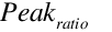 = Ratio of peak scattered
beam transmittance to scattered beam transmittance at direct
normal incidence.
= Ratio of peak scattered
beam transmittance to scattered beam transmittance at direct
normal incidence.
 = Ratio of peak scattered
visible transmittance to scattered visible transmittance at
direct normal incidence.
= Ratio of peak scattered
visible transmittance to scattered visible transmittance at
direct normal incidence.
 = diffuse solar
reflectance of the screen material
= diffuse solar
reflectance of the screen material
 = diffuse visible
reflectance of the screen material
= diffuse visible
reflectance of the screen material
 = beam solar
transmittance due to reflectance (scattering)
= beam solar
transmittance due to reflectance (scattering)
 = beam visible
transmittance due to reflectance (scattering)
= beam visible
transmittance due to reflectance (scattering)
The reflected (scattered) transmittance of incident beam
radiation is an empirical model derived by curvefitting
results from optical ray trace modeling. Ray traces were
performed for a range of screen aspect ratios, diffuse screen
reflectances, and relative solar azimuth and altitude angles.
The surface of the screen cylinders was assumed to be
diffusely reflecting, having the optical properties of a
Lambertian surface. The transmitted flux due to reflection was
determined by a hemispherical detector on the transmitted side
of the screen.
These two components of beam solar transmittance are then
used to specify the properties for beam-to-beam and
beam-to-diffuse transmittance for the screen based on the user
selection for Reflected Beam Transmittance Accounting Method
in the WindowMaterial:Screen
object. The calculations below apply to both the solar and
visible beam solar transmittance.
If the user selects DoNotModel, the direct beam
transmittance is set to Tbeam and the
reflected (scattered) portion of the beam solar transmittance
is ignored:
where
 = direct-to-direct beam
transmittance of the screen (output report variable Surface Window
Screen Beam to Beam Solar Transmittance)
= direct-to-direct beam
transmittance of the screen (output report variable Surface Window
Screen Beam to Beam Solar Transmittance)
 = direct-to-diffuse beam
transmittance of the screen (output report variable Surface Window
Screen Beam to Diffuse Solar Transmittance)
= direct-to-diffuse beam
transmittance of the screen (output report variable Surface Window
Screen Beam to Diffuse Solar Transmittance)
 = direct-to-direct
visible transmittance of the screen
= direct-to-direct
visible transmittance of the screen
 = direct-to-diffuse
visible transmittance of the screen
= direct-to-diffuse
visible transmittance of the screen
If the user selects Model as Direct Beam, the reflected
(scattered) portion of the beam solar transmittance is added
to the direct beam transmittance Tbeam in
the same solid angle and direction of the unattenuated solar
beam:
If the user selects Model as Diffuse Beam, the direct beam
transmittance is set to Tbeam and the
reflected (scattered) portion of the beam solar transmittance
is modeled as diffuse hemispherical radiation:
Screen Beam Reflectance[LINK]
The screen reflectance (overall value for the screen
assembly, accounting for the screen material itself and the
open spaces between the screen material) is calculated by
first subtracting the direct-to-direct screen transmittance
from the unit incident beam. This approximates the fraction of
incident beam solar radiation striking the screen that is not
inwardly transmitted. The result is then multiplied by the
screen material diffuse reflectance ρsc. The
inwardly scattered transmittance is then subtracted from this
quantity to obtain an approximate value for the screen’s
reflectance Rsc to beam radiation incident as a
function of the relative angles of incident radiation. This
equation is used for both beam and visible reflectance:
Screen Beam Absorptance[LINK]
The screen absorptance (overall value for the screen
assembly, accounting for the screen material itself and the
open spaces between the screen material) is calculated as the
quantity of the unit incident flux (1) less the
directly-transmitted component
Tdir,dirmultiplied by the quantity 1 minus
the screen material diffuse reflectance.
Screen Diffuse
Properties[LINK]
The transmittance of the screen to half-hemispherical
diffuse (sky) radiation is calculated by performing a
finite-element-summation, approximately equivalent to an
integration over the solid angle of the beam transmittance,
assuming uniform radiance. This single-number screen diffuse
transmittance is then multiplied by the irradiance incident on
the screen from a uniform half-hemisphere of sky- or
ground-reflected radiation to determine the level of
additional flux transmitted by the screen to the window from
the diffuse sky or ground. The sun angles shown in the figure
below represent the solar altitude angle (θ) and solar azimuth
angle (Ф) in polar coordinates. These angles are used to
calculate the average diffuse-to-diffuse properties for
screens in the following derivations.
The screen transmittance to diffuse radiation
Tdif,dif (γ, ρsc) is computed
as the integrated average of the combined beam transmittance
Ttot(γ, ρ, θ, Ф) over the directions of
incidence using spherical coordinates (θ, Ф) in which the
z-axis is perpendicular to the plane of the screen. Using a
finite element computation, this is:
where
 = solar altitude angle in
polar coordinates [radians]
= solar altitude angle in
polar coordinates [radians]
 = solar azimuth angle in
polar coordinates [radians]
= solar azimuth angle in
polar coordinates [radians]
 = diffuse-diffuse
transmittance (output report variable Surface Window
Screen Diffuse to Diffuse Solar Transmittance)
= diffuse-diffuse
transmittance (output report variable Surface Window
Screen Diffuse to Diffuse Solar Transmittance)
Similarly, the reflectance of the screen to diffuse
radiation is given by
There is an assumption in both of these formulas that the
brightness of the sky (or ground) diffuse radiation is the
same for all directions. For this reason, the solar azimuth
angle Ф and solar altitude angle θ have a range of 0 to  (instead of
  to
to  ) because the screen is assumed
to have identical optical properties for radiation incident at
the same angles on either side of a vertical or horizontal
plane perpendicular to the screen.
) because the screen is assumed
to have identical optical properties for radiation incident at
the same angles on either side of a vertical or horizontal
plane perpendicular to the screen.
Since the screen direct transmittance model is derived with
respect to a different coordinate axis labeling, a coordinate
transform is needed in order to calculate the diffuse optical
properties. In these calculations, for each spherical solar
coordinates (θ, Ф) we need the corresponding screen relative
solar coordinates (α’, φ’) to evaluate the screen
transmittance model for that direction.
For each θ and Ф in the summation, the corresponding values
for the relative solar altitude α’ and relative solar azimuth
φ’ needed to calculate screen transmittance are determined
with the following coordinate transform equations:
The absorptance of the screen to diffuse incident radiation
is calculated by subtracting the diffuse transmittance and
diffuse reflectance from unity as follows:
Screen/Glass
System Properties for Short-Wave Radiation[LINK]
The combined system properties of the screen/glass
combination are calculated using the properties of the screen
in combination with the bare glass material properties.
Interreflections of radiation between the screen and glass
surfaces are included. The following infinite series serves as
an example for calculating the combined screen/glass system
properties. The terms of the series are built up as
illustrated in the following figure. The terms shown at the
right of the figure represent each term in the infinite series
for the combined screen/glass property (beam transmittance in
this example).
For the example of beam transmittance, the incident solar
beam strikes the screen at the incident angle associated with
the current relative azimuth and altitude angle. The incident
beam splits into reflected and transmitted components at the
screen. The transmitted component is attenuated as it passes
through the screen material by the screen’s beam transmittance
( , shown as
 in the figure and equations
below) at this incident angle. The reflected (scattered)
transmittance of incident solar beam is also shown at this
point and will be discussed later in this section. As the
attenuated solar beam continues on towards the front glass
surface, a portion of the screen-transmitted beam splits at
the window surface into transmitted and reflected components.
The reflected component reflects off the front surface of the
glass material (
in the figure and equations
below) at this incident angle. The reflected (scattered)
transmittance of incident solar beam is also shown at this
point and will be discussed later in this section. As the
attenuated solar beam continues on towards the front glass
surface, a portion of the screen-transmitted beam splits at
the window surface into transmitted and reflected components.
The reflected component reflects off the front surface of the
glass material (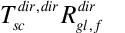 ) and the
transmitted component continues to travel through the glass
material and is further attenuated by the glass beam
transmittance. Thus the first term of the combined
screen/glass solar beam transmittance is shown as
) and the
transmitted component continues to travel through the glass
material and is further attenuated by the glass beam
transmittance. Thus the first term of the combined
screen/glass solar beam transmittance is shown as 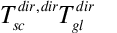 . Interreflections are accounted
for by following the beam as it continues to reflect off the
front surface of the glass material and the back surface of
the screen material. Continuing on with the glass-reflected
beam ( ) described above,
this beam strikes the back surface of the screen material at
the same incident angle as the incident solar beam. This
reflected beam is also assumed to be a collimated beam (solid
lines) which strikes the back surface of the screen material
and reflects as hemispherically-diffuse radiation (dotted
lines). The reflective property of the screen material used
here is the beam reflectance calculated at the incident solar
angle (
. Interreflections are accounted
for by following the beam as it continues to reflect off the
front surface of the glass material and the back surface of
the screen material. Continuing on with the glass-reflected
beam ( ) described above,
this beam strikes the back surface of the screen material at
the same incident angle as the incident solar beam. This
reflected beam is also assumed to be a collimated beam (solid
lines) which strikes the back surface of the screen material
and reflects as hemispherically-diffuse radiation (dotted
lines). The reflective property of the screen material used
here is the beam reflectance calculated at the incident solar
angle ( ). A single ray of
this diffuse light will be followed through the remaining
steps and represents the energy associated with
all diffuse rays interreflecting between the
screen and glass layers. To determine the second term of the
combined screen/glass beam transmittance, the
diffusely-reflected ray (
). A single ray of
this diffuse light will be followed through the remaining
steps and represents the energy associated with
all diffuse rays interreflecting between the
screen and glass layers. To determine the second term of the
combined screen/glass beam transmittance, the
diffusely-reflected ray ( )
passes through and is attenuated by the glass layer. Since
this ray originates from diffuse reflection, the attenuation
of this ray is accounted for using the diffuse transmittance
property of the glass. Thus, the second term is shown as
)
passes through and is attenuated by the glass layer. Since
this ray originates from diffuse reflection, the attenuation
of this ray is accounted for using the diffuse transmittance
property of the glass. Thus, the second term is shown as  . Defining the remaining terms
continues in a similar fashion using diffuse properties of
both the screen and glass material. Notice that the
3rd and 4th terms shown below are
similar to the 2nd term, but additional terms are
raised to increasing powers.
. Defining the remaining terms
continues in a similar fashion using diffuse properties of
both the screen and glass material. Notice that the
3rd and 4th terms shown below are
similar to the 2nd term, but additional terms are
raised to increasing powers.
The screen/glass system transmittance equation shown in the
figure above is repeated here in an alternate format to
emphasize the recurring nature of the infinite series. This
equation represents the final solar beam transmittance
equation for the screen/glass combination. The recurring terms
are shown as a summation of a quantity raised to the n power,
with n ranging from 0 to infinity. Since the quantity 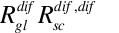 is less than 1, the summation
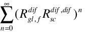 converges and can be
expressed as
converges and can be
expressed as 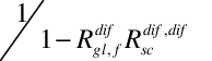 . Since the
reflected (scattered) transmittance of incident solar beam
(
. Since the
reflected (scattered) transmittance of incident solar beam
( ) and the diffusely
reflecting beam
) and the diffusely
reflecting beam  are both
assumed to be hemispherically diffuse radiation, the reflected
(scattered) transmittance of incident solar beam is added to
the infinite series as shown below.
are both
assumed to be hemispherically diffuse radiation, the reflected
(scattered) transmittance of incident solar beam is added to
the infinite series as shown below.
where
 = screen/glass system
beam transmittance (output report variable Surface Window
Screen and Glazing System Beam Solar Transmittance)
= screen/glass system
beam transmittance (output report variable Surface Window
Screen and Glazing System Beam Solar Transmittance)
Properties for beam absorptance of the individual glass
layers and screen/glass combination are derived in a similar
fashion to the transmittance calculation described above.
Diffuse transmittance and absorptance of individual glass
layers and the screen/glass combination are also shown
here.


where
 = glass layer beam
absorptance including interreflections with screen
material
= glass layer beam
absorptance including interreflections with screen
material
 = beam absorptance of
screen material including interreflections with glass
= beam absorptance of
screen material including interreflections with glass
 = screen/glass system
diffuse transmittance (output report variable Surface Window
Screen and Glazing System Diffuse Solar Transmittance)
= screen/glass system
diffuse transmittance (output report variable Surface Window
Screen and Glazing System Diffuse Solar Transmittance)
 = glass layer diffuse
absorptance including interreflections with screen
material
= glass layer diffuse
absorptance including interreflections with screen
material
 = diffuse absorptance of
screen material including interreflections with glass
= diffuse absorptance of
screen material including interreflections with glass
Screen/Glazing
System Properties for Long-Wave Radiation[LINK]
The program calculates how much long-wave radiation is
absorbed by the screen and by the adjacent glass surface. The
effective long-wave emissivity (equal to the long-wave
absorptance on a wavelength-by-wavelength basis or over the
same spectral range) of an exterior screen, taking into
account reflection of long-wave radiation between the glass
and screen, is given by
where is the long-wave
reflectance of the outermost glass surface facing an exterior
screen, and it is assumed that the long-wave transmittance of
the glass is zero.
The effective outermost (for exterior screen) glass surface
emissivity when the screen is present is
The effective inside surface emissivity is the sum of the
effective screen and effective glass emissivities:
The effective temperature of the screen/glazing combination
that is used to calculate the window’s contribution to the
zone’s mean radiant temperature (MRT) is given by
Solar
Radiation Transmitted and Absorbed by a Window/Screen
System[LINK]
Let the direct solar incident on the window be
where is the fraction of
the window that is sunlit (determined by the shadowing
calculations), is the direct
normal solar irradiance, and
is the angle of incidence.
Let be the irradiance on
the window due to diffuse solar radiation from the sky
(W/m2) and let be
the irradiance on the window due to diffuse solar radiation
from the ground (W/m2).
Then we have the following expressions for different
classes of transmitted and absorbed solar radiation for the
window/screen system, all in W/m2:
Direct and diffuse solar entering zone from incident
direct solar:
Direct solar absorbed by screen:
Direct solar absorbed by glass layers:
Diffuse solar entering zone from incident diffuse
solar:
Diffuse solar absorbed by screen:
Diffuse solar absorbed by glass layers:
Complex
Fenestration Calculation Module[LINK]
This section describes detailed method for modeling complex
fenestration systems, including shading devices and general
fenestration attachments. This detailed method primarily
refers to the optical side of modeling complex fenestration
systems. Thermal modeling is done according to ISO 15099
standard, which is described in the Window
Heat Balance Calculation section with the addition of
deflection and vacuum glazing systems modeling and some
modifications to shading layer algorithms, which is described
in Shading Device Thermal Model section. Optical caclulations
in this method are done using Bidirectional Scattering
Distribution Function (BSDF) approach. The concept behind BSDF
is based on the definition of descrete set of incident and
outgoing angles, which fully describes optical performance of
any system, simple or complex, limited only by the resolution
of angular discretization. In this method each layer, as well
as the whole system is described by a matrix of incident and
outgoing angles.
Complex
Fenestration Solar-Optical Calculations[LINK]
Solar
radiation calculation outline[LINK]
For solar radiation calculations, each of the layers as
well as entire glazing system can be represented with the set
of Bi-directional Scattering Distribution Functions or BSDF,
consisting of Bi-directional Reflectance Distribution Function
or BRDF and Bi-directional Transmittance Distribution Function
or BTDF. Each function is a matrix 145 x 145 that describes
reflectance or transmittance distribution in the outgoing
hemisphere for each incident angle in the incidence
hemisphere. For each function there is forward and back
matrix, for a total of 4 145 x 145 matrices. Depending on the
purpose of calculations, description of entire glazing system
is divided into solar and visible spectrum, which means that
there can be 8 matrices describing visible and complete solar
spectrums. Reflectance and transmittance being non-dimnsional
ratios of reflected or transmitted energy over incident
energy, in order to get total reflected and transmitted energy
it is necessary to supply vector of incident solar energy,
which usually consists of direct and diffuse
radition.Specifics of calculations of direct and diffuse solar
radiationis be described in some detail in oncoming
chapters.
Scattering
(Non-Specular) Glazing and Shading Devices[LINK]
A general scattering fenestration system is characterized
by BTDFs and BRDFs, which were described above. Given an
incident direction p(I), and an
incident irradiance E(
p(I)), the transmitted radiance in
the outgoing direction p(T) is
where the function T is the BTDF. In the absence of a
source of effectively plane-parallel incident radiation (such
as direct sunlight)
dE(p(I)) is an
infinitesimal quantity, and the right side of the equation
must be summed over the irradiance from all incident
directions to produce the outgoing radiance:
A similar equation gives the reflected radiance in the
direction p(R):
We can express the irradiance in terms of the exterior
luminance, S, in that direction,
Figure 89: Irradiance geometry
which allows one to express the transmittance of exterior
radiation to produce the total outgoing radiance from the
fenestration into the room in a particular direction:
The negative sign is added to account for the fact that
p(I) and n have
opposite sign for incoming radiation.
The radiance in equation is emitted from the back side of
the element of area shown in Figure 89. Considering a second
surface, viewing the back side of the fenestration system, we
can use equation to calculate the irradiance on surface 2,
This expression, however, contains a number of new
quantities, such as  , the
element of solid angle for incoming radiation as seen from
surface 2. We can sort this out by referring to Figure 90 and
making some changes and clarifications in notation.
, the
element of solid angle for incoming radiation as seen from
surface 2. We can sort this out by referring to Figure 90 and
making some changes and clarifications in notation.
Figure 90: Radiation exchange between two surface
elements
In this figure we consider that surface 1 is the back side
of the fenestration system, and surface 2 is some other
surface in the room that receives the transmitted solar
radiation through the fenestration system. We consider
infinitesimal elements dA(1) and
dA(2) of the two surfaces, and define
vector surface elements by
dA(1)=dA(1)n(1)
and
dA(1)=dA(1)n(1).
The quantity r in the figure denotes a vector
pointing from surface 1 to surface 2, the magnitude of which
is the distance r between the two surface elements.
This is used to define two unit vectors: 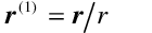 is a unit vector pointing from
surface element 1 to surface element 2, and
is a unit vector pointing from
surface element 1 to surface element 2, and  is a unit vector pointing from
surface element 2 back to surface element 1. The unit vector
p(T) in equation is in fact
is a unit vector pointing from
surface element 2 back to surface element 1. The unit vector
p(T) in equation is in fact  . The shaded quadrilaterals in
the figure are the projected area elements normal to
r. Since the areas are infinitesimal, all the
radiation leaving one surface element and arriving at the
other will be in the direction r, so that all
radiation will be contained within the parallelepiped defined
by the dashed lines (parallel to r) joining
the corners of the two surface elements. It follows that the
area dA(2) is not independent of
dA(1). The figure also shows the solid
angle that has been denoted d(I,2) above,
which is the solid angle subtended by
dA(1) as seen from
dA(2) and is given by
. The shaded quadrilaterals in
the figure are the projected area elements normal to
r. Since the areas are infinitesimal, all the
radiation leaving one surface element and arriving at the
other will be in the direction r, so that all
radiation will be contained within the parallelepiped defined
by the dashed lines (parallel to r) joining
the corners of the two surface elements. It follows that the
area dA(2) is not independent of
dA(1). The figure also shows the solid
angle that has been denoted d(I,2) above,
which is the solid angle subtended by
dA(1) as seen from
dA(2) and is given by
The net power from surface element 1 to surface element 2
is
where 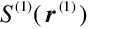 is the radiance
leaving surface element 1 in the direction of surface element
2, and vice-versa for
is the radiance
leaving surface element 1 in the direction of surface element
2, and vice-versa for 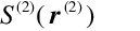 . In
this case, the latter is zero and the former is the quantity
called
S(T)(p(T))
above. Given equation , we can recognize the quantity
multiplying the radiance as the solid angle
d(I,2) times the projected area of
surface element 2 perpendicular to r. But the
expression is symmetrical in the two surface elements, so we
could also express it as
. In
this case, the latter is zero and the former is the quantity
called
S(T)(p(T))
above. Given equation , we can recognize the quantity
multiplying the radiance as the solid angle
d(I,2) times the projected area of
surface element 2 perpendicular to r. But the
expression is symmetrical in the two surface elements, so we
could also express it as
where
The superscript (T) is used here because the solid angle
element pertains to the direction
p(T). In the particular case under
discussion that restricts attention to those directions for
which the outgoing radiation strikes surface element 2. We can
now rewrite equation as
and since, as can readily be seen from Figure 90,  , this becomes
Substituting equation for
S(T)(p(T), we
obtain a propagation equation for outside radiation passing
through the window and arriving at surface element 2:
or, in terms involving only irradiance,
Comparing these two equations with equations and , we can
see that physically they represent the processes of (a)
propagation of radiation outgoing at one surface (initially,
the sky “surface”), where it is characterized by radiance, to
incidence on a second surface, characterized by irradiance,
followed (b) transmittance, which converts incoming radiation
traveling in a given direction to outgoing radiation in a
different set of directions, characterized again by radiance.
We can make the former of these processes explicit by defining
a propagation function. Considering the first surface element
to be located at a position specified by the vector
x(1) and the second at
x(2), then radiation leaving
surface 1 in a direction p(1) and
arriving at surface 2 in a direction
p(2) produces an irradiance given
by
where the propagation function L is defined by
The spatial dependence is inserted to guarantee that the
geometrical relations in Figure 90 are preserved. The delta
functions in direction and spatial vectors are the
mathematically standard -distributions defined so that
for an arbitrary function f. [In equations and the
integration is assumed to be over all possible values of
either direction or position, so that the vectors
p(2) and
x(2) are necessarily within the
domain of integration.]
Physical Caveats[LINK]
In equations and the functions T and R pertain to the
overall glazing system, and are assumed to be averaged over
both wavelength and polarization with appropriate weightings.
[EnergyPlus considers wavelength only in that it distinguishes
between radiation in the longwave thermal IR region and in the
shortwave solar/visible region. (In considering daylighting,
there is a further limitation to the visible region.) In this
discussion we are concerned solely with the shortwave
solar/visible region.] While fenestration properties may
depend on both wavelength and polarization, for externally
incident radiation this dependence is taken into account in
the calculation and averaging of T and R. However, both the
wavelength distribution (within the solar region) and the
polarization state of the outgoing radiation will generally be
different from that of the incident radiation. This is not a
feature peculiar to non-specular fenestration systems; it is
also true of specular ones, and may in fact be more important
there. For most interior surfaces, where the radiation is
either absorbed or diffusely reflected (and where both
processes are assumed wavelength and polarization
independent), this is of no importance, but in the case of
either interior windows or the back-reflectance from exterior
windows, it could in principle cause errors, unless proper
account is taken in specifying T and R for these cases.
Discretization: The
LBNL Method[LINK]
A series of 6 papers (Papamichael, Klems et al. 1988; Klems
1994A; Klems 1994B; Klems and Warner 1995; Klems and Kelley
1996; Klems, Warner et al. 1996) formulated the LBNL method of
characterizing scattering fenestration systems. The relevant
aspects of that method will be summarized here. This method
has been incorporated into the WINDOW (from LBNL 2012)
computer program.
The method begins by approximating the integrals in
equations and by finite sums. It does this by defining a set
of finite solid angle elements  that covers the relevant solid
angle hemisphere (whether incident, transmitted or reflected
directions). Each solid angle element is characterized by a
direction pi, and it is
assumed that this may be substituted for any direction within
the solid angle element. This set of solid angle elements and
corresponding directions is termed a basis. Note that, since
pi is a two-dimensional
vector, enumerating the solid angle elements with a single
index i implicitly includes specifying an ordering of
the direction vectors. Equation then becomes
that covers the relevant solid
angle hemisphere (whether incident, transmitted or reflected
directions). Each solid angle element is characterized by a
direction pi, and it is
assumed that this may be substituted for any direction within
the solid angle element. This set of solid angle elements and
corresponding directions is termed a basis. Note that, since
pi is a two-dimensional
vector, enumerating the solid angle elements with a single
index i implicitly includes specifying an ordering of
the direction vectors. Equation then becomes
and equation becomes
Referring to the definition of the propagation function in
equation and properties of the -distribution in equation , we
see that the integrals in the summation will all be zero,
except when
pj(2) is
contained in the solid angle element i.
In that case the integration produces
pi(1)=
pj(2). We can
retain the formal summation by utilizing the
finite-dimensional form of the -distribution, known as the
Kronicker delta, ij:
Then the integral becomes
where the function is defined as
and the superscript (s) refers to the surface.
The LBNL method, which focuses on glazing systems
consisting of plane-parallel layers, makes particular
assumptions that allow one to ignore the spatial dependence of
L. Since the only effect of the function  in equation is to require that if
the expression is formally integrated over two separate
surface areas, only the parts of the integration that satisfy
the geometric constraints will contribute (in effect, the
integration is over only one of the surfaces), we will drop
the spatial dependence in the present discussion and replace
it later when we consider the total energy transfer between
different surfaces.
in equation is to require that if
the expression is formally integrated over two separate
surface areas, only the parts of the integration that satisfy
the geometric constraints will contribute (in effect, the
integration is over only one of the surfaces), we will drop
the spatial dependence in the present discussion and replace
it later when we consider the total energy transfer between
different surfaces.
Equations (without the delta distribution in
x) and are then considered to define the
components of a diagonal matrix,
Considering the radiance in the various basis directions to
be the components of a vector,
equation becomes
which has the obvious character of a series of matrix
multiplications. (Note that the superscript (T) here means
transmitted, not the matrix operation transpose.) Similarly,
the reflectance matrix elements are
The method then identifies the infinitesimal directional
irradiances in equation with the components of an irradiance
vector,
and equations - can be rewritten as matrix equations,
(These are for radiation incident on the front surface of
the fenestration; there is a similar set of equations for
radiation incident on the back surface and propagating in an
opposite sense to that in the above equations.)
In the LBNL method, these equations are used extensively to
calculate the overall properties of a fenestration system from
those of its component layers. Here we will assume that the
components of the system property matrices are given at input.
These may be from a calculation by WINDOW or determined by
some other method. The quantities needed for each fenestration
are:
Table 32: Fenestration properties needed for the
calculation
| Exterior Window |
 |
Front Transmittance matrix
elements |
 |Back Reflectance matrix
elements
|Back Reflectance matrix
elements
 |In-situ absorptance of
nth layer for front incidence
|In-situ absorptance of
nth layer for front incidence
 |In-situ absorptance of
nth layer for back incidence
|In-situ absorptance of
nth layer for back incidence
Interior Window| |Front
Transmittance matrix elements
|Front
Transmittance matrix elements
 |Back Transmittance matrx
elements
|Back Transmittance matrx
elements
 |Front Reflectance matrix
elements
|Front Reflectance matrix
elements
 |Back Reflectance matrix
elements
|Back Reflectance matrix
elements
 |In-situ absorptance of
nth layer for front incidence
|In-situ absorptance of
nth layer for front incidence
 |In-situ absorptance of
nth layer for back incidence
|In-situ absorptance of
nth layer for back incidence
The transmittance and reflectance are overall system
properties. (For daylighting calculations, one also needs the
transmittance and reflectance averaged over the visible
spectrum only; the quantities indicated in the table pertain
to the entire solar spectrum.) For the optical calculations we
do not need to know anything about the individual layers
making up the fenestration. However, the thermal calculation
of heat flow through the fenestration requires knowledge of
the amount of radiation absorbed in each of the fenestration
layers. As indicated in the table, we therefore need the
in-situ layer absorptance for each layer, referenced to the
incident surface. This is denoted  for the fraction of the
ith component of the irradiance incident
on the front surface of the fenestration that is absorbed in
layer n, with a similar quantity,
for the fraction of the
ith component of the irradiance incident
on the front surface of the fenestration that is absorbed in
layer n, with a similar quantity,  , for irradiance incident on the
back surface. The term “in-situ layer absorptance” is used
because these are not simply the absorptance of the layer, but
include the transmittance and interreflection by other layers
of the system prior to the absorptance in layer n.
The absorptance is a row vector, having possibly a different
value for each direction of the incident irradiance, so that
for an irradiance EiF on the
front surface of a fenestration and
EiB on the back surface, the
power Qn absorbed per unit area in layer
n would be
, for irradiance incident on the
back surface. The term “in-situ layer absorptance” is used
because these are not simply the absorptance of the layer, but
include the transmittance and interreflection by other layers
of the system prior to the absorptance in layer n.
The absorptance is a row vector, having possibly a different
value for each direction of the incident irradiance, so that
for an irradiance EiF on the
front surface of a fenestration and
EiB on the back surface, the
power Qn absorbed per unit area in layer
n would be
(In the vector/matrix language,  )
)
Bases and Coordinate
Systems[LINK]
The introduction of a basis or multiple bases is a bit more
complicated than indicated in the text preceding equation .
There for transmission we need coordinates describing incoming
radiation on one surface of the physical layer and outgoing
radiation at the second (opposite) surface, while reflection
adds the need for coordinates describing outgoing radiation at
the first surface. Back transmittance and reflectance add the
requirement for coordinates describing incoming radiation at
the second surface. The usual way of assigning coordinates to
radiation involves specifying its line of propagation relative
to the local surface normal. This means that there are
separate coordinate systems for the first and second surfaces,
and that, moreover, the description is different for incoming
and outgoing radiation: for incoming radiation one is
specifying a unit vector pointing toward the source of the
radiation (i.e., antiparallel to the
direction of propagation), while for outgoing radiation one is
specifying a unit vector in the direction of propagation of
the radiation. In principle, then, one needs four coordinate
systems or bases (for each physical layer), and the process of
transmission or reflection involves a discontinuous transition
between an input basis and an output basis.
The LBNL method used by WINDOW uses a particular choice of
coordinate systems in which incoming radiation at the first
surface and outgoing radiation at the second are described by
one coordinate system, while the same coordinate system
reflected through the layer is used to describe incoming
radiation at the second surface and outgoing radiation at the
first. The reason for this choice is that it greatly
simplifies the matrix representations: specular transmittance
or reflectance is always represented by a diagonal matrix, one
can mix matrices representing forward or backward incidence
processes, and all of the coordinate systems have propagation
matrices with the same representation, so in effect there is
one matrix rather than four.
The point of this discussion is that the components of the
transmittance and reflectance matrices, and the layer
absorptance vectors, depend on the definition of these four
bases. If they were generated by WINDOW, then they assume the
particular coordinate system described above. (If they were
produced by some other means, they may be specified in yet
some other coordinate system.) While the LBNL coordinate
system gives an intuitive description of outgoing radiation,
as a description of incoming radiation it is very unintuitive.
And in any case, the coordinate system is different from that
of EnergyPlus. It will be necessary to translate the matrices
and vectors into the correct EnergyPlus coordinate system.
Matching
the WINDOW6 Calculation to EnergyPlus[LINK]
It is useful to have some sense of how well the basis
normally used in WINDOW calculations matches the requirements
of EnergyPlus. In using a BSDF window, a user would presumably
be interested in the directionality of the transmitted
radiation; if the size of the solid angle bins in the basis is
large compared to the solid angle subtended by the typical
surface in a zone, then that directional information will be
lost. On the other hand, if the bins are very small compared
to this solid angle, then (since EnergyPlus does not consider
the spatial variations within a surface) the directions are
being oversampled. Since the calculation time will be
proportional to the number of matrix elements, which is the
square of the number of basis directions, oversampling is to
be avoided.
Because of the great variety of buildings that may be
modeled with EnergyPlus, and because the user has control over
the basis for the BSDF properties, it is not possible to
answer this question in a definitive way. Here we consider the
effect of the normal WINDOW basis in a typical perimeter
office space, 10 ft wide, 15 ft deep and 11 ft high. It is
assumed to have a window 9 ft wide by 6 ft high, with the sill
height 3 ft. The window is placed to have a 4 in inner
reveal.
The normal WINDOW “full” basis has 145 output directions.
Figure 91 shows how the window and the solid angle bin project
onto the inner surfaces for three of those directions. In each
case the solid angle bin is projected from the window center,
and the window edges are projected along the central ray.
In general, the basis appears to be reasonably matched to
the calculation, with neither a loss of angular detail nor
great oversampling.
Figure 91: Transmitted Radiation in Three Directions for a
Perimeter Office. (a) =0º; (b) =40º, =15º; (c) =70º,
=67.5º. and are the normal spherical angle coordinates in
a right-handed coordinate system where y points up and z is
normal to the window p
Complex
Fenestrations in EnergyPlus[LINK]
EnergyPlus models the exterior radiance in two parts, a
moving sun radiance  and a
constant-shape direction-dependent sky radiance
and a
constant-shape direction-dependent sky radiance  . The intensities of these vary
with time. For the solar radiation there is a single sky
radiance model. For daylight calculations the treatment is
similar for exterior luminance, except that there are a number
of user-selectable sky luminance models. Here we will discuss
radiance; the treatment of luminance is analogous.
. The intensities of these vary
with time. For the solar radiation there is a single sky
radiance model. For daylight calculations the treatment is
similar for exterior luminance, except that there are a number
of user-selectable sky luminance models. Here we will discuss
radiance; the treatment of luminance is analogous.
The direct normal solar intensity (at a given time) is
and if we let
where the shape function for the sky radiance model,
s, is defined so that
then the global solar irradiance on a horizontal surface at
a given time is
It must be understood that in equation the integration
region 2 means integration over the sky hemisphere, and that
s(p) is zero for
upward-going directions.
With the sky radiance shape
s(p) specified in the
EnergyPlus code, the angular size of the sun  known, and the solar zenith angle
 calculated in the code, the
two hourly input quantities
I(D)(t) and
I(G)(t) determine the exterior
radiance for any given hour.
calculated in the code, the
two hourly input quantities
I(D)(t) and
I(G)(t) determine the exterior
radiance for any given hour.
In this context, the transmitted radiance for a complex
fenestration system given in equation becomes
where the incoming hemisphere viewed by the fenestration
has been broken up into four parts. The viewed sky (excluding
the part containing the sun) is  , the viewed ground is
  , the part subtended by the sun
is (Sun), and the part subtended by one or more
exterior surfaces (shading or reflecting objects) is
(Sf). These solid angles must exclude the exterior
surfaces. The symbol H represents a Helmholtz
function: Its value is one if its logical argument is true,
zero otherwise. It has been inserted into the equation to
account for those times when the sun is behind an exterior
object. Where there are multiple exterior shading or
reflecting objects, (Sf) may consist of several
regions that may be disjoint or connected, depending on the
exterior geometry. As indicated in the equation,
(Sun) is time-dependent, to account for the sun’s
movement; (Gnd) and (Sf) are fixed,
but as written
, the part subtended by the sun
is (Sun), and the part subtended by one or more
exterior surfaces (shading or reflecting objects) is
(Sf). These solid angles must exclude the exterior
surfaces. The symbol H represents a Helmholtz
function: Its value is one if its logical argument is true,
zero otherwise. It has been inserted into the equation to
account for those times when the sun is behind an exterior
object. Where there are multiple exterior shading or
reflecting objects, (Sf) may consist of several
regions that may be disjoint or connected, depending on the
exterior geometry. As indicated in the equation,
(Sun) is time-dependent, to account for the sun’s
movement; (Gnd) and (Sf) are fixed,
but as written  has a time
dependence induced by the exclusion of the solid angle
subtended by the sun. So that we can discuss the parts
separately, we break the outgoing radiance down by source:
has a time
dependence induced by the exclusion of the solid angle
subtended by the sun. So that we can discuss the parts
separately, we break the outgoing radiance down by source:
By subtracting the radiation from the part of the sky
hidden by the sun from  and
adding it back into S(Sky) we can remove
the time dependence of (Sky):
and
adding it back into S(Sky) we can remove
the time dependence of (Sky):
Now in equation the integral is to be evaluated without
regard to the sun position, and therefore  is time-independent.
We can further simplify equation by noting that the angular
size of the sun is small, and both
s(p(I)) and
T(p(T),
p(I)) can be considered as
constant over the range of directions in (Sun).
We can therefore evaluate them at the direction
p(Sun)(t) of the center of the sun
and move them out of the integration, resulting in
In this equation we have dropped the explicit time
dependence, but p(Sun),
(Sun), I(D), and
I(Sky) are time-varying, while
(Sun) is simply the constant angular size of the
sun.
We separate the reflected radiance
S(Sf) into separate components for each
surface,
The individual shading surface reflected radiances are
then
The solid angle of integration in this expression is
subtended by the portion of the exterior reflecting surface
n viewed by the fenestration; if one surface lies
behind another, the hidden part of its surface is removed from
the solid angle it subtends. This is summarized by the
requirement
(This requirement will need to be modified to handle the
case of transmitting exterior surfaces.)
S(Refl,n) is time dependent because the
incident radiation on the surface depends on the sun position.
**Equation must be evaluated after the exterior surface
shading or reflectance calculations, in order to enforce the
requirement that
Finally, the transmitted radiance from the ground-reflected
exterior radiation is
Here, not only is there the requirement that
but also the incident radiation on the ground may be
affected by shading or reflection from exterior surfaces.
Since this is dependent on the sun position,
S(Gnd) is time dependent, as indicated in
equation .
Applying the discretization of the previous section and the
definitions in equations -, we can rewrite equation as
where
is the sky radiance shape factor evaluated at the central
direction of the ith solid angle bin. A “T”
superscript has been added on the left-hand side of the
equation to denote that S is the transmitted outgoing
radiance (due to incident sky radiation for the fenestration
under discussion). The stipulation 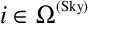 on the summation means that the
sum is to include only those solid angle elements for which
the sky is viewed by the fenestration. This is essentially a
shading calculation, in addition to a restriction to
downward-going incident directions. We anticipate the result
of this calculation by defining a sky geometric factor,
on the summation means that the
sum is to include only those solid angle elements for which
the sky is viewed by the fenestration. This is essentially a
shading calculation, in addition to a restriction to
downward-going incident directions. We anticipate the result
of this calculation by defining a sky geometric factor,  :
:
Then we can carry out the summation over all downward
directions and write
Similarly, equation becomes
where Vi^(Sf, n)^ is another geometric
view factor, defined analogously to equation , giving the
fraction of the solid angle  that views the exterior surface n. Note that
The quantity  is in fact
the reflected radiance at a particular location on the
nth exterior surface—the location where the
direction
pi(I)
intersects the surface. (This statement will become more
precise when the spatial dependence dropped from equation is
re-inserted.) This surface is assumed to have either a diffuse
reflectance (n) or a specular reflectance
^(sp, n)^. (Both properties are possible
simultaneously, but EnergyPlus assumes that an exterior
surface is either diffusing or specular, but not both.) The
reflectance is assumed uniform over the surface, but the
particular location (effectively, the image of the
fenestration projected onto surface n) may or may not view the
sky, or, at a particular time, the sun. We denote the incident
irradiance of the surface n by
is in fact
the reflected radiance at a particular location on the
nth exterior surface—the location where the
direction
pi(I)
intersects the surface. (This statement will become more
precise when the spatial dependence dropped from equation is
re-inserted.) This surface is assumed to have either a diffuse
reflectance (n) or a specular reflectance
^(sp, n)^. (Both properties are possible
simultaneously, but EnergyPlus assumes that an exterior
surface is either diffusing or specular, but not both.) The
reflectance is assumed uniform over the surface, but the
particular location (effectively, the image of the
fenestration projected onto surface n) may or may not view the
sky, or, at a particular time, the sun. We denote the incident
irradiance of the surface n by  . This irradiance pertains only
to the surface n (in the present EnergyPlus calculation) and
is independent of the fenestration or its basis. We attach the
subscript i simply as a reminder that (2) the irradiance
pertains to the portion of the surface that is viewed by the
solid angle element
. This irradiance pertains only
to the surface n (in the present EnergyPlus calculation) and
is independent of the fenestration or its basis. We attach the
subscript i simply as a reminder that (2) the irradiance
pertains to the portion of the surface that is viewed by the
solid angle element  of the
fenestration f (which would become important if the EnergyPlus
shading calculations were modified to relax the assumption of
uniform incident irradiance on exterior surfaces) and that the
irradiance pertains only to those surfaces n that are viewed
by the solid angle element i. For specularly reflecting
surfaces, we make the following definitions: First, within the
set of basis solid angles
of the
fenestration f (which would become important if the EnergyPlus
shading calculations were modified to relax the assumption of
uniform incident irradiance on exterior surfaces) and that the
irradiance pertains only to those surfaces n that are viewed
by the solid angle element i. For specularly reflecting
surfaces, we make the following definitions: First, within the
set of basis solid angles  ,
let s(t) identify the one containing the sun
direction at time t, and let r(t) identify
the one containing the specular reflection direction of the
sun at time t. We then define a contingent direct
beam irradiance, which we denote by
,
let s(t) identify the one containing the sun
direction at time t, and let r(t) identify
the one containing the specular reflection direction of the
sun at time t. We then define a contingent direct
beam irradiance, which we denote by  . This irradiance is non-zero
only if
. This irradiance is non-zero
only if 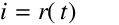 this direction is
such that i is the specularly reflected direction for the
surface n. If this is the case, then
this direction is
such that i is the specularly reflected direction for the
surface n. If this is the case, then  is the incident direct beam
irradiance. With this definition,
is the incident direct beam
irradiance. With this definition,
If we then define normalized irradiance factors U
by  and
and  , where
 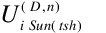 denotes the fraction of the beam
solar that irradiates the surface for a given sun direction.
It is evaluated during the shading calculation, as indicated
by the notation Sun(tsh). With these definitions we
can rewrite the equation as
denotes the fraction of the beam
solar that irradiates the surface for a given sun direction.
It is evaluated during the shading calculation, as indicated
by the notation Sun(tsh). With these definitions we
can rewrite the equation as
and equation becomes, in terms of the incident
irradiances,
and in terms of the normalized irradiance factors,
The specularly reflected term can be removed from the sum,
since only one value of i can contribute:
and
which separates specular and diffuse reflectance from the
exterior surfaces.
With respect to shading and reflection of exterior
radiation into the fenestration, the exterior reveal surfaces
can be treated as additional diffusely reflecting exterior
surfaces.
Ground radiation is treated in the same way as radiation
reflected from interior surfaces, except that one sums only
over upward-going incident directions, and the ground is
assumed to be diffusely reflecting. The transmitted radiance
from ground reflectance is
In this equation, the symbol  is shorthand for a spatial
calculation. The solid angle region
is shorthand for a spatial
calculation. The solid angle region  views (from various points over
the fenestration area) some spatial region of the ground. The
symbol
views (from various points over
the fenestration area) some spatial region of the ground. The
symbol  denotes the incident
irradiance on the ground over this spatial region. In the
absence of shading, this would be simply
denotes the incident
irradiance on the ground over this spatial region. In the
absence of shading, this would be simply  ; shading requires a more complex
calculation. Currently the EnergyPlus code does a Monte-Carlo
calculation: rays are randomly generated from the window, when
they strike the ground a calculation is made to determine
whether that point receives direct solar radiation and what
portion of the sky it views (reflected radiation from surfaces
is neglected). Here we would perform that calculation for each
region of the ground i viewed by a basis solid angle element,
instead of generating random rays from the window. We denote
the results of that calculation by
; shading requires a more complex
calculation. Currently the EnergyPlus code does a Monte-Carlo
calculation: rays are randomly generated from the window, when
they strike the ground a calculation is made to determine
whether that point receives direct solar radiation and what
portion of the sky it views (reflected radiation from surfaces
is neglected). Here we would perform that calculation for each
region of the ground i viewed by a basis solid angle element,
instead of generating random rays from the window. We denote
the results of that calculation by  , where the U’s are
average viewing factors for the sun and sky, calculated as
part of the shading calculation (which is indicated by the
subscript tsh: Sun(tsh) is the sun direction
as specified by the shading calculation. This then gives
, where the U’s are
average viewing factors for the sun and sky, calculated as
part of the shading calculation (which is indicated by the
subscript tsh: Sun(tsh) is the sun direction
as specified by the shading calculation. This then gives
The transmitted radiance from direct beam radiation is
This introduces yet one more geometric view factor:  is zero if the sun direction
s(t) is not i; if i=s(t)
it is the fraction of the fenestration area irradiated by the
direct sun. Equation uses the fact that the angular size of
the sun is smaller than any basis solid angle element, and
that EnergyPlus treats the sun and circumsolar region as a
point source [hence the absence of the sky correction in
equation ].
is zero if the sun direction
s(t) is not i; if i=s(t)
it is the fraction of the fenestration area irradiated by the
direct sun. Equation uses the fact that the angular size of
the sun is smaller than any basis solid angle element, and
that EnergyPlus treats the sun and circumsolar region as a
point source [hence the absence of the sky correction in
equation ].
At this point we have developed separate expressions for a
fenestration’s transmitted radiance in a particular direction
depending on the exterior source of the radiation. These
expressions utilize the discretized BTDF of the fenestration
in the form of transmittance matrix elements over an angular
basis. The exterior geometry is re-expressed in the form of
geometric view factors in this basis. In the process, the
explicit time dependence of the exterior radiation has been
reduced to the time-varying direct and diffuse solar
intensities and the solar position. The time dependence of the
solar position, however, consists merely in specifying, for a
particular time, which of the basis solid angle elements
contains the solar direction. The entire exterior geometry
necessary for the fenestration transmittance calculation can
therefore be pre-calculated.
We begin with the discretized form of equation , in which
we also modify the surface notation. In that equation, the
surfaces involved are termed (1) and (2), where radiation is
outgoing from surface 1 and incoming to surface 2. Here
radiation is outgoing from the inner surface of the
fenestration, so we label that surface (f). The receiving
surface is one of the surfaces of the zone in which the
fenestration is located. We number those surfaces with the
index k, so the receiving surface is labeled
(k). Equation then becomes
or, noting that  (where
the superscript T is retained in case the incoming and
outgoing bases are defined differently),
(where
the superscript T is retained in case the incoming and
outgoing bases are defined differently),
If we integrate this expression over the fenestration area
A(f) we obtain the total power leaving the
fenestration surface in direction j; however, all of
that power may not reach surface k: some may strike
the inner window reveal or a different zone surface. If we
define a spatial projection operator by
where
x(k)
is in the plane of surface k, and a geometric form
factor by
then
The total power leaving the fenestration (in any direction)
and arriving at surface k is then
Substituting equations , , , , into equation yields a
series of expressions for the total power arriving at surface
k (by transmission through fenestration f) from each
of the sources of exterior radiation. However, the equations
for transmitted radiation describe an infinitesimal region,
which means that the radiation in a given direction will
always come from one source. When one integrates the
transmitted power over the fenestration surface, one
encounters the problem that for this direction different parts
of the fenestration area may receive radiation from different
sources. Also, for a given outgoing direction, the projection
of a receiving surface back onto the fenestration may produce
an image that covers only part of the fenestration area, and
this image may not be identical with the part of the area that
receives incident radiation from a particular source. The most
important origin of this problem is the existence of inner and
outer window reveals, as illustrated in Figure 92.
Figure 92: Mismatch of irradiated and viewed fenestration
areas for different incident and outgoing directions
In this figure, the portion of the fenestration area not
viewed by the plane of surface k is instead viewed by
one or more of the inner window reveals. Similarly, the
portion of the fenestration not irradiated in the figure is in
fact irradiated by diffusely reflected radiation from the
outer window reveals. We can account for this by replacing the
area A(f) in equation with the overlap
area  **(dark shaded in the
figure), where “Src” stands for the source of the incident
radiation. This area is defined by
**(dark shaded in the
figure), where “Src” stands for the source of the incident
radiation. This area is defined by
The total power at the interior surface k for each
source of radiation then becomes
If we define a series of solar irradiation factors, Z, that
describe the fraction of the radiation incident on the
fenestration due to a given exterior radiation source that is
ultimately incident on the interior surface k,
then equations through become
The notation s(t) appearing in a subscript in
several of the above equations refers to the basis direction
for which the sun direction is contained in the basis solid
angle element. This is of course time dependent. What is meant
here is that at any given time the particular basis element
containing the sun is to be picked out. (If no basis element
for the fenestration contains the sun at a given time, then
the corresponding view factor—and therefore irradiance or
absorption factor—is zero.) It is therefore necessary to
tabulate those quantities with an s(t) subscript for
all basis directions s that could possibly contain
the sun direction (and for r(t), all basis directions
that could possibly contain the reflected sun angle for the
surface n). This is a set considerably smaller than that of
all incoming basis directions. Figure 93 illustrates this
point for direct irradiation of fenestrations in three
different orientations in a building at a particular latitude,
using the W6 full basis, which has 145 incoming directions. In
the worst case (west-facing) one only needs to consider around
50 of these, with much fewer needed in other orientations. The
specific numbers for a given fenestration will depend on the
choice of basis, orientation and latitude. The basis direction
values can of course be interpolated where greater directional
resolution is warranted. In equation the specular direction
r(t) is uniquely determined by the sun direction
s(t), so the Z factor does not need an additional
index for s.
Figure 93: Sun Paths and Incident Basis for Three Window
Orientations, 38º N. Latitude. The nodal positions (blue dots)
for a W6 full basis are compared with the summer solstice (red
curve) and winter solstice (green curve) solar paths. Solar
paths for other days of the year will lie between these two
extremes. (Note: the basis points are to be interpreted as the
direction of a vector pointing from the fenestration to the
sun.) (a) South facing. (b) West facing. (c) North facing (the
winter path is off the figure (i.e., the window is shaded);
allowed paths will be outside the red path.
The reason for the definition of the Z factors is that to a
great extent they can be precalculated, so that within the
hourly calculation only equations - need to be used. In
addition, there are fewer Z factors to be stored than
transmittance matrix elements. The storage determinants for
the foregoing calculations are summarized in the following
table.
Table 33: Determination of array sizes
Parameters
NBasis Number of elements in the
(incoming or outgoing) basis
NSun Number of basis directions that
may be sun directions (depends on fenestration orientation
 Number of sun
directions that give significantly different ground
irradiation conditions, as seen by fenestration
Number of sun
directions that give significantly different ground
irradiation conditions, as seen by fenestration
NSf Number of reflecting surfaces
viewable by fenestration (depends on fenestration
orientation)
 Number of time steps for
which surface n is sunlit (depends on orientation of
surface n; determined during shading calculation)
Number of time steps for
which surface n is sunlit (depends on orientation of
surface n; determined during shading calculation)
 Number of basis
directions that may be reflected sun directions from surface
n (depends on orientation of fenestration and surface
n).
Number of basis
directions that may be reflected sun directions from surface
n (depends on orientation of fenestration and surface
n).
NIntSurf Number of interior surfaces in
the zone containing the fenestration
NLayers Number of thermal layers in the
fenestration system
Arrays
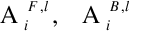 Absorptance vector
element; NBasis
Absorptance vector
element; NBasis
Tij Transmittance matrix element;
NBasisX NBasis
 Sky viewed fraction;
one-dimensional, NBasis
Sky viewed fraction;
one-dimensional, NBasis
 Fraction of surface
n viewed; NBasis X
NSf
Fraction of surface
n viewed; NBasis X
NSf
(n), ^(sp, n)^ Surface
n diffuse, specular reflectance;
NSf (already stored by E+)
 Fraction of the image of
 on surface n that
views the sun when it is in direction Sun(tsh);
NBasis X NSf X
on surface n that
views the sun when it is in direction Sun(tsh);
NBasis X NSf X 
 Fraction of
  that views ground;
NBasis
that views ground;
NBasis
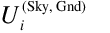 Fraction of sky radiation
received by the image of
Fraction of sky radiation
received by the image of  on
the ground; NBasis
on
the ground; NBasis
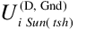 Fraction of direct solar
radiation for sun direction Sun(tsh) received by image of
Fraction of direct solar
radiation for sun direction Sun(tsh) received by image of  on ground;
  **X\\
NBasis
**X\\
NBasis
 Fraction of fenestration
area irradiated by direct solar radiation for direction
i, given that sun angle is s(t);
NSun~~X NBasis
Fraction of fenestration
area irradiated by direct solar radiation for direction
i, given that sun angle is s(t);
NSun~~X NBasis
 Fraction of radiation
in direction j leaving fenestration interior that arrives
at surface k; NBasis X
NIntSurf
Fraction of radiation
in direction j leaving fenestration interior that arrives
at surface k; NBasis X
NIntSurf
 Sky irradiation factor;
NIntSurf
Sky irradiation factor;
NIntSurf
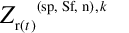 Exterior surface specular
irradiation factor;
Exterior surface specular
irradiation factor;  X
NSf X NIntSurf
X
NSf X NIntSurf
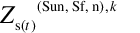 Exterior surface
direct-diffuse irradiation factor;
Exterior surface
direct-diffuse irradiation factor;  X NSf X
NIntSurf
X NSf X
NIntSurf
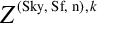 Exterior surface sky
irradiation factor; NSf X
NIntSurf
Exterior surface sky
irradiation factor; NSf X
NIntSurf
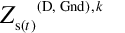 Ground-reflected direct
solar irradiaton factor (given sun direction s(t));
Ground-reflected direct
solar irradiaton factor (given sun direction s(t));
 X
NIntSurf
X
NIntSurf
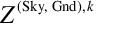 Ground-reflected diffuse
solar irradiation factor; NIntSurf
Ground-reflected diffuse
solar irradiation factor; NIntSurf
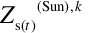 Direct solar irradiation
factor; NSun X
NIntSurf
Direct solar irradiation
factor; NSun X
NIntSurf
 Sky absorption factor;
NLayers
Sky absorption factor;
NLayers
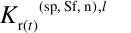 Exterior surface
specular absorption factor; NSf X
Exterior surface
specular absorption factor; NSf X  X NLayers
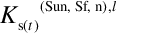 Exterior surface
diffusely reflected direct sun absorption factor;
NSf X
Exterior surface
diffusely reflected direct sun absorption factor;
NSf X  X
NLayers
X
NLayers
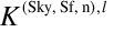 Exterior surface
reflected sky radiation absorption factor;
NSf X NLayers
Exterior surface
reflected sky radiation absorption factor;
NSf X NLayers
 Ground-reflected
direct solar absorption factor;
Ground-reflected
direct solar absorption factor;  X NLayers
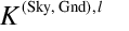 Ground-reflected sky
radiation absorption factor; NLayers
Ground-reflected sky
radiation absorption factor; NLayers
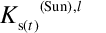 Direct sunlight
absorption factor; NSun X
NLayers
Direct sunlight
absorption factor; NSun X
NLayers
For thermal calculations it is necessary to know the energy
absorbed in each layer of the fenestration. This depends only
on the incident geometry, but otherwise is calculated in the
same manner as the solar flux incident on interior surfaces.
For a given layer l of a fenestration f, we define a
source-referenced absorption factor, K(source),l. This is the
amount of energy absorbed in layer l divided by the relevant
solar intensity (which might be beam, diffuse, or reflected
beam or diffuse, depending on the source of the radiation).
These absorption factors and the resultant source-specific
absorbed solar powers are calculated by the analogs [see
equation of equations through :
Use of the basis in the above discussion has been mostly
implicit, but it should nevertheless be clear that the
essential feature of the basis is that it is a two-element
list (i.e., a 2 X N array): it associates with an incident (i)
or outgoing (j) direction index a vector pi (or pj ) that is a
unit vector giving the direction of the radiation, the
specification of which is two angles in some coordinate
system. The incident and outgoing bases of course must match
the matrix elements of the fenestration properties. These
bases will (certainly in the case of WINDOW program; probably
in the case of other input sources) have a structure: ordering
of the elements, etc. However, after the initialization of the
hourly loop calculation, this structure will be irrelevant:
EnergyPlus will retain only those incoming and outgoing
directions that are essential to the calculation with (one
would hope, most of) the others combined into irradiation
factors. At this point, the basis will truly be an arbitrary
list. It follows that the specification of the basis in the
EnergyPlus input should be determined by (1) the source of
fenestration property data, and (2) user convenience.
A related point concerns the specification of a basis for
specular glazings, i.e., multiple layers of glass. These
fenestrations are both specular (input direction=output
direction) and axially symmetric. These properties have
different effects on the calculation.
The specular property means that one should not be using
equation at all to describe the transmittance. Instead, one
should use the equation
This equation is shoehorned into the integral calculation
of equation through the use of a delta function in the
incident direction vector, resulting (after the
discretization) in a diagonal matrix for the transmittance (or
reflectance). The outgoing radiance element on the diagonal
would be calculated as
Tiiii, where
multiplication by ii substitutes for
integration over the basis solid angle element. For a specular
glazing,  , so one recovers
the correct transmittance when one does the multiplication.
However, there is still a problem in principle: For a specular
fenestration, the angular spread of the outgoing radiation
will be that of the source, which for direct sunlight is very
small; the calculation, however, assumes the angular spread of
the basis element. This problem disappears in the geometric
approximation to be used in EnergyPlus: by considering only
the central direction of each basis element, the outgoing
radiation in that direction is essentially assumed to be
specular, so the blurring in the discretization is undone.
, so one recovers
the correct transmittance when one does the multiplication.
However, there is still a problem in principle: For a specular
fenestration, the angular spread of the outgoing radiation
will be that of the source, which for direct sunlight is very
small; the calculation, however, assumes the angular spread of
the basis element. This problem disappears in the geometric
approximation to be used in EnergyPlus: by considering only
the central direction of each basis element, the outgoing
radiation in that direction is essentially assumed to be
specular, so the blurring in the discretization is undone.
The axial symmetry of conventional glazings means that the
transmittance (or reflectance) depends on only the incident
angle, not the azimuthal angle about the normal to the
fenestration plane. So if one specifies the diagonal elements
of the matrix, all of the terms with the same incident angles
but different azimuthal angles will be the same. One could
alternatively specify only the specular transmittance at each
of the incident angle values, provided one also indicated that
it was for an axially symmetric fenestration. Since expanding
this set of values to the equivalent diagonal elements is a
trivial calculation, how one specifies a specular glazing is
completely a question of user convenience. For example, if one
were dealing with the WINDOW full basis, would it be more
user-friendly to specify
 , for 145 values, 135
of which are repeats of the previous value
, for 145 values, 135
of which are repeats of the previous value
 for 9 values of
incident angle, i ?
for 9 values of
incident angle, i ?
Interior
Solar Radiation Transmitted by Complex Fenestration[LINK]
Diffuse
Solar Radiation Transmitted by Complex Fenestration[LINK]
Distribution of solar radiation transmitted through
exterior window is divided on diffuse and direct part.
Diffuse solar transmitted through exterior complex
fenestration and absorbed in interor walls is calculated and
treated in same way as described in the section on Initial
Distribution of Diffuse Solar Transmitted through Exterior and
Interior Windows. Even though that BSDF is given for various
directions, for purpose of diffuse solar radiation,
transmittance and reflectances of fenestration system is
integrated over incoming and outgoing hemisphere. Because
incoming diffuse solar radiation is divided on ground and sky
parts, integration of incoming hemisphere is also perfomed
over ground and sky part (see equation .
Direct
Solar Radiation Transmitted by Complex Fenestration[LINK]
Direct solar (beam) transmitted through exterior window is
using same overlap calculations (see Figure 48) for each
outgoing basis direction. For certain sun position, algorithm
calculatates equivalent incoming beam number. The inside beam
solar irradiance is calculated in similar manner as described
in the section titled Interior Beam Radiation.
i = exterior window number
Nextwin = number of exterior windows in
zone
Nout = Beam number of exterior windows
in zone
CosInci = cosine of angle of incidence
of beam on exterior window i
TBmk,j = beam-to-beam transmittance of
exterior window i at incidence direction k outgoing
direction j
Λk,j = lambda value of exterior window
i at incidence direction k~~for outgoing direction
j
Aoverlapk,j(SurfNum) = beam solar
irradiated area of surface SurfNum projected back
onto the plane of exterior window i for incoming
direction k and outgoing direction j (the Aoverlap’s
for an exterior window sum up to the glazed area of the
window)
AbsIntSurf(SurfNum) = inside face solar
absorptance of surface SurfNum
A(SurfNum) = area of surface SurfNum
[m2]
Equation is valid as long as surface which is hit by
transmitted solar radiation is not another complex
fenestration. In that case, for beam which is transmitted from
other exterior window and reaches back surface of this window,
angle of incidence needs to be taken into account.
Interior
Solar Absorbed by Complex Fenestration[LINK]
Solar radiation absorbed in window layers is coming from
three sources: Diffuse radiation from sky and ground, direct
radiation from the sun and beam radiation coming from the sun
and it is transmitted through other exterior windows.
Diffuse Radiation from Sky and Ground
Energy absorbed in the layers and which originates from
diffuse radiation from sky and ground is represented by
following equation:
where,
WinSkyFtAbs(Lay) = front absorptance averaged over
sky for layer (Lay) and window belonging to Surf
WinSkyGndAbs(Lay) = front absorptance averaged
over ground for layer (Lay) and window belonging to Surf
SkySolarInc = incident diffuse solar from the
sky
GndSolarInc = incident diffuse solar from the
ground
Direct Radiation from the Sun
Energy absorbed in the layers and which originates from
direct solar radiation is given by following equation:
where,
AWinSurf(SurfNum,Lay) – is time step value of
factor for beam absorbed in fenestration glass layers
BeamSolar – Current beam normal solar
irradiance
Factor for time step value is given by equation:

where,
WinBmFtAbs(Lay,HourOfDay,TimeStep) – is front
directional absorptance for given layer and time
CosInc – cosine of beam solar incident angle
SunLitFract – sunlit fraction without shadowing
effects of frame and divider
OutProjSLFracMult(HourOfDay) - Multiplier on
sunlit fraction due to shadowing of glass by frame and divider
outside projections.
Direct Solar Radiation Coming from Sun and it is
Transmitted Through Other Windows
Direct solar radiation transmitted through other windows is
using solar overlap calculations described in the section on
Overlapping Shadows. Overlapping is used to determine amount
of energy transferred through the window is hitting certain
surface. That is used to calculate energy absorbed in walls
and same approach will be used to calculate energy absorbed in
window layers (equation ). In case when receiving surface is
complex fenestration, it is not enought just to apply equation
because factor AbsIntSurf is now depending of incoming angle
which is defined through front and back directional
absorptance matrices. It would mean that for each outgoing
directions of transmitting complex fenestration, algorithm
would need to determine what is best matching basis direction
of receiving surface. Best receiving direction is used to
determine absorptance factors which will be used in equation .
It is important to understand that for basis definition, each
unit vector defining one beam is going towards surface, which
would mean that best matching directions from surface to
surface will actually have minimal dot product.
where,
Bestin – is best matching receiving direction
basis dot product (ink)
outp – current transmitting complex fenestration
direction
in1, …, inN – set of receiving
complex fenestration basis directions
Result of equation is minimal dot product, which
corresponds to best matching direction of receiving surface.
If we mark that direction with index k, then equation
becomes:
where,
AbsIntSurfk(SurfNum) – directional
absorptance for the receiving surface for the best matching
direction
Everything else is same as described in equation .
Klems, J. H. 1994A. “A New Method for Predicting the Solar
Heat Gain of Complex Fenestration Systems: I. Overview and
Derivation of the Matrix Layer Calculation.”. ASHRAE
Transactions. 100(pt.1): 1073-1086.
Klems, J. H. 1994B. “A New Method for Predicting the Solar
Heat Gain of Complex Fenestration Systems: II. Detailed
Description of the Matrix Layer Calculation.”. ASHRAE
Transactions. 100(pt.1): 1073-1086.
Klems, J. H. 1995. “Measurements of Bidirectional Optical
Properties of Complex Shading Devices.”. ASHRAE Transactions.
101(pt 1; Symposium Paper CH-95-8-1(RP-548)): 791-801.
Klems, J. H. 1996. “A Comparison between Calculated and
Measured SHGC for Complex Glazing Systems.”. ASHRAE
Transactions. 102(Pt. 1; Symposium Paper AT-96-16-1):
931-939.
Klems, J. H. 1996. “Calorimetric Measurements of
Inward-Flowing Fraction for Complex Glazing and Shading
Systems.”. ASHRAE Transactions. 102(Pt. 1; Symposium Paper
AT-96-16-3): 947-954.
Papamichael, K. J. 1998. “Determination and Application of
Bidirectional Solar-Optical Properties of Fenestration
Systems.”. Cambridge, MA: 13th National Passive Solar
Conference.

Window Calculation Module[LINK]
This section describes two potential modeling approaches for Windows. The first (layer by layer) is implemented. The second, simple approach, reuses the layer-by-layer approach but converts an arbitrary window performance into an equivalent single layer.
The primary Window calculation is a layer-by-layer approach where windows are considered to be composed of the following components, only the first of which, glazing, is required to be present:
In the following, the description of the layer-by-layer glazing algorithms is based on material from Finlayson et al., 1993. The frame and divider thermal model, and the shading device optical and thermal models, are new to EnergyPlus.
A second approch has been developed where windows are modeled in a simplified approach that requires minimal user input that is processed to develop and equivalent layer that then reuses much of the layer-by-model. This “Simple Window Construction: model is described below.
Optical Properties of Glazing[LINK]
The solar radiation transmitted by a system of glass layers and the solar radiation absorbed in each layer depends on the solar transmittance, reflectance and absorptance properties of the individual layers. The absorbed solar radiation enters the glazing heat balance calculation that determines the inside surface temperature and, therefore, the heat gain to the zone from the glazing (see “Window Heat Balance Calculation”). The transmitted solar radiation is absorbed by interior zone surfaces and, therefore, contributes to the zone heat balance. In addition, the visible transmittance of the glazing is an important factor in the calculation of interior daylight illuminance from the glazing.
Table: Variables in Window Calculations
Mathematical variable|Description|Units||FORTRAN variable ———————|———–|—–||—————- T|Transmittance|-|- R|Reflectance|-|- Rf, Rb|Front reflectance, back reflectance|-|- Ti,j|Transmittance through glass layers i to j|-|- Tdirgl|Direct transmittance of glazing|-|- Rfi,j, Rbi,j|Front reflectance, back reflectance from glass layers i to j|-|- Rdirgl,f, Rdirgl,b|Direct front and back reflectance of glazing|-|- Afi, Abi|Front absorptance, back absorptance of layer i|-|- N|Number of glass layers|-|Nlayer λ|Wavelength|microns|Wle Es(λ)|Solar spectral irradiance function|W/m2-micron|E V(λ)|Photopic response function of the eye|-|y30 φ|Angle of incidence (angle between surface normal and direction of incident beam radiation)|Rad|Phi τ|Transmittivity or transmittance|-|tf0 ρ|Reflectivity or reflectance|-|rf0, rb0 α|Spectral absorption coefficient|m-1|- d|Glass thickness|M|Material%Thickness n|Index of refraction|-|ngf, ngb κ|Extinction coefficient|-|- β|Intermediate variable|-|betaf, betab P, p|A general property, such as transmittance|-|- τsh|Shade transmittance|-|Material%Trans ρsh|Shade reflectance|-|Material%ReflectShade αsh|Shade absorptance|-|Material%AbsorpSolar τbl,ρbl,αbl|Blind transmittance, reflectance, absorptance|-|- Q, G, J|Source, irradiance and radiosity for blind optical properties calculation|W/m2|- Fij|View factor between segments i and j|-|- fswitch|Switching factor|-|SwitchFac T|Transmittance|-|- R|Reflectance|-|- Rf, Rb|Front reflectance, back reflectance|-|- Ti,j|Transmittance through glass layers i to j|-|- Rfi,j, Rbi,j|Front reflectance, back reflectance from glass layers i to j|-|- Afi, Abi|Front absorptance, back absorptance of layer i|-|- N|Number of glass layers|-|Nlayer λ|Wavelength|microns|Wle Es(λ)|Solar spectral irradiance function|W/m2-micron|E R(λ)|Photopic response function of the eye|-|y30 φ’|Relative azimuth angle (angle between screen surface normal and vertical plane through sun, Ref. Figure 86)|Rad|SunAzimuthToScreenNormal α’|Relative altitude angle (angle between screen surface horizontal normal plane and direction of incident beam radiation, Ref. Figure 86)|Rad|SunAltitudeToScreenNormal ρsc|Beam-to-diffuse solar reflectance of screen material|-|Screens%ReflectCylinder γ|Screen material aspect ratio|-|Screens%ScreenDiameterTo|SpacingRatio Α|Spectral absorption coefficient|m-1|- D|Glass thickness|M|Material%Thickness N|Index of refraction|-|ngf, ngb Κ|Extinction coefficient|-|- Β|Intermediate variable|-|betaf, betab P, p|A general property, such as transmittance|-|-
Glass Layer Properties[LINK]
In EnergyPlus, the optical properties of individual glass layers are given by the following quantities at normal incidence as a function of wavelength:
Transmittance, T
Front reflectance, Rf
Back reflectance, Rb
Here “front” refers to radiation incident on the side of the glass closest to the outside environment, and “back” refers to radiant incident on the side of the glass closest to the inside environment. For glazing in exterior walls, “front” is therefore the side closest to the outside air and “back” is the side closest to the zone air. For glazing in interior (i.e., interzone) walls, “back” is the side closest to the zone in which the wall is defined in and “front” is the side closest to the adjacent zone.
Glass Optical Properties Conversion[LINK]
Conversion from Glass Optical Properties Specified as Index of Refraction and Transmittance at Normal Incidence[LINK]
The optical properties of uncoated glass are sometimes specified by index of refraction, n,and transmittance at normal incidence, T.
The following equations show how to convert from this set of values to the transmittance and reflectance values required by Material:WindowGlass. These equations apply only to uncoated glass, and can be used to convert either spectral-average solar properties or spectral-average visible properties (in general, n and T are different for the solar and visible). Note that since the glass is uncoated, the front and back reflectances are the same and equal to the R that is solved for in the following equations.
Given n and T, find R:
Example:
T = 0.86156
n = 1.526
Simple Window Model[LINK]
EnergyPlus includes an alternate model that allows users to enter in simplified window performance indices. This model is accessed through the WindowMaterial:SimpleGlazingSystem input object and converts the simple indices into an equivalent single layer window. (In addition a special model is used to determine the angular properties of the system – described below). Once the model generates the properties for the layer, the program reuses the bulk of the layer-by-layer model for subsequent calculations. The properties of the equivalent layer are determined using the step by step method outlined by Arasteh, Kohler, and Griffith (2009). The core equations are documented here. The reference contains additional information.
The simplified window model accepts U and SHGC indices and is useful for several reasons:
Note: This use of U and SHGC to describe the thermal properties of windows is only appropriate for specular glazings.
While it is important to include the ability to model windows with only U-value and SHGC, we note that any method to use U and SHGC alone in building simulation software will inherently be approximate. This is due primarily to the following factors:
SHGC combines directly transmitted solar radiation and radiation absorbed by the glass which flows inward. These have different implications for space heating/cooling. Different windows with the same SHGC often have different ratios of transmitted to absorbed solar radiation.
SHGC is determined at normal incidence; angular properties of glazings vary with number of layers, tints, coatings. So products which have the same SHGC, can have different angular properties.
Window U-factors vary with temperatures.
Thus, for modeling specific windows, we recommend using more detailed data than just the U and SHGC, if at all possible.
The simplified window model determines the properties of an equivalent layer in the following steps.
Step 1. Determine glass-to-glass Resistance.[LINK]
Window U-values include interior and exterior surface heat transfer coefficients. The resistance of the bare window product, or glass-to-glass resistance is augmented by these film coefficients so that,
Where,
The values for and
and  depend on U and are calculated
using the following correlations.
depend on U and are calculated
using the following correlations.
So that the glass-to-glass resistance is calculated using,
Because the window model in EnergyPlus is for flat geometries, the models are not necessarily applicable to low-performance projecting products, such as skylights with unisulated curbs. The model cannot support glazing systems with a U higher than 7.0 because the thermal resistance of the film coefficients alone can provide this level of performance and none of the various resistances can be negative.
Step 2. Determine Layer Thickness.[LINK]
The thickness of the equivalent layer in units of meters is calculated using,
Step 3. Determine Layer Thermal Conductivity[LINK]
The effective thermal conductivity, , of the equivalent layer is
calculated using,
, of the equivalent layer is
calculated using,
Step 4. Determine Layer Solar Transmittance[LINK]
The layer’s solar transmittance at normal incidence, , is calculated using correlations
that are a function of SHGC and U-Factor.
, is calculated using correlations
that are a function of SHGC and U-Factor.
And for U-values between 3.4 and 4.5, the value for is interpolated using results of
the equations for both ranges.
is interpolated using results of
the equations for both ranges.
Step 5. Determine Layer Solar Reflectance[LINK]
The layer’s solar reflectance is calculated by first determining the inward flowing fraction which requires values for the resistance of the inside and outside film coefficients under summer conditions, and
and
 respectively. The
correlations are
respectively. The
correlations are
And for U-values between 3.4 and 4.5, the values are interpolated using results from both sets of equations.
The inward flowing fraction, , is then calculated using
The the solar reflectances of the front face, , and back face,
  , are calculated using,
The thermal absorptance, or emittance, is take as 0.84 for both the front and back and the longwave transmittance is 0.0.
Step 6. Determine Layer Visible Properties[LINK]
The user has the option of entering a value for visible transmittance as one of the simple performance indices. If the user does not enter a value, then the visible properties are the same as the solar properties. If the user does enter a value then layer’s visible transmittance at normal incidence, ,is set to that value. The
visible light reflectance for the back surface is calculated
using,
,is set to that value. The
visible light reflectance for the back surface is calculated
using,
The visible light reflectance for the front surface is calculated using,
Step 7. Determine Angular Performance[LINK]
The angular properties of windows are important because during energy modeling, the solar incidence angles are usually fairly high. Angles of incidence are defined as angles from the normal direction extending out from the window. The simple glazing system model includes a range of correlations that are selected based on the values for U and SHGC. These were chosen to match the types of windows likely to have such performance levels. The matrix of possible combinations of U and SHGC values have been mapped to set of 28 bins shown in the following figure.
There are ten different correlations, A thru J, for both transmission and reflectance. The correlations are used in various weighting and interpolation schemes according the figure above. The correlations are normalized against the performance at normal incidence. EnergyPlus uses these correlations to store the glazing system’s angular performance at 10 degree increments and interpolates between them during simulations. The model equations use the cosine of the incidence angle, , as the
independent variable. The correlations have the form:
, as the
independent variable. The correlations have the form:
The coefficient values for a, b, c, d, and e are listed in the following tables for each of the curves.
Application Issues[LINK]
EnergyPlus’s normal process of running the detailed layer-by-layer model, with the equivalent layer produced by this model, creates reports (sent to the EIO file) of the overall performance indices and the properties of the equivalent layer. Both of these raise issues that may be confusing.
The simplified window model does not reuse all aspects of the detailed layer-by-layer model, in that the angular solar transmission properties use a different model when the simple window model is in effect. If the user takes the material properties of an equivalent glazing layer from the simple window model and then re-enters them into just the detailed model, then the performance will not be the same because of the angular transmission model will have changed. It is not proper use of the model to re-enter the equivalent layer’s properties and expect the exact level of performance.
There may not be exact agreement between the performance indices echoed out and those input in the model. This is expected with the model and the result of a number of factors. For example, although input is allowed to go up to U-7 W/m2∙K, the actual outcome is limited to no higher than about 5.8W/m2∙K. This is because the thermal resistance to heat transfer at the surfaces is already enough resistance to provide an upper limit to the conductance of a planar surface. Sometimes there is conflict between the SHGC and the U that are not physical and compromises need to be made. In general, the simple window model is intended to generate a physically-reasonable glazing that approximates the input entered as well as possible. But the model is not always be able to do exactly what is specified when the specifications are not physical.
References[LINK]
Arasteh, D., J.C. Kohler, B. Griffith, Modeling Windows in EnergyPlus with Simple Performance Indices. Lawrence Berkeley National Laboratory. In Draft. Available at http://windows.lbl.gov/win_prop/ModelingWindowsInEnergyPlusWithSimplePerformanceIndices.pdf
Glazing System Properties[LINK]
The optical properties of a glazing system consisting of N glass layers separated by nonabsorbing gas layers (Figure 76. Schematic of transmission, reflection and absorption of solar radiation within a multi-layer glazing system.) are determined by solving the following recursion relations for Ti,j , the transmittance through layers i to j; Rfi,j~~and Rbi,j, the front and back reflectance, respectively, from layers i to j; and Aj , the absorption in layer j. Here layer 1 is the outermost layer and layer N is the innermost layer. These relations account for multiple internal reflections within the glazing system. Each of the variables is a function of wavelength.
In Eq. Ti,j = 1 and Ri,j = 0 if i<0 or j>N.
As an example, for double glazing (N=2) these equations reduce to
If the above transmittance and reflectance properties are input as a function of wavelength, EnergyPlus calculates “spectral average” values of the above glazing system properties by integrating over wavelength:
The spectral-average solar property is
The spectral-average visible property is
where is the solar
spectral irradiance function and
is the solar
spectral irradiance function and  is the photopic response function
of the eye. The default functions are shown in Table 27 and
Table 28. They can be overwritten by user defined solar and/or
visible spectrum using the objects Site:SolarAndVisibleSpectrum
and Site:SpectrumData.
They are expressed as a set of values followed by the
corresponding wavelengths for values.
is the photopic response function
of the eye. The default functions are shown in Table 27 and
Table 28. They can be overwritten by user defined solar and/or
visible spectrum using the objects Site:SolarAndVisibleSpectrum
and Site:SpectrumData.
They are expressed as a set of values followed by the
corresponding wavelengths for values.
If a glazing layer has optical properties that are roughly constant with wavelength, the wavelength-dependent values of Ti,i , Rfi,i~~and Rbi,i in Eqs. to can be replaced with constant values for that layer.
Table 27: Solar spectral irradiance function.
Air mass 1.5 terrestrial solar global spectral irradiance values (W/m2-micron) on a 37o tilted surface. Corresponds to wavelengths in following data block. Based on ISO 9845-1 and ASTM E 892; derived from Optics5 data file ISO-9845GlobalNorm.std, 10-14-99.[LINK]
Wavelengths (microns) corresponding to above data block 0.3000,0.3050,0.3100,0.3150,0.3200,0.3250,0.3300,0.3350,0.3400,0.3450, | 0.3500,0.3600,0.3700,0.3800,0.3900,0.4000,0.4100,0.4200,0.4300,0.4400, | 0.4500,0.4600,0.4700,0.4800,0.4900,0.5000,0.5100,0.5200,0.5300,0.5400, | 0.5500,0.5700,0.5900,0.6100,0.6300,0.6500,0.6700,0.6900,0.7100,0.7180, | 0.7244,0.7400,0.7525,0.7575,0.7625,0.7675,0.7800,0.8000,0.8160,0.8237, | 0.8315,0.8400,0.8600,0.8800,0.9050,0.9150,0.9250,0.9300,0.9370,0.9480, | 0.9650,0.9800,0.9935,1.0400,1.0700,1.1000,1.1200,1.1300,1.1370,1.1610, | 1.1800,1.2000,1.2350,1.2900,1.3200,1.3500,1.3950,1.4425,1.4625,1.4770, | 1.4970,1.5200,1.5390,1.5580,1.5780,1.5920,1.6100,1.6300,1.6460,1.6780, | 1.7400,1.8000,1.8600,1.9200,1.9600,1.9850,2.0050,2.0350,2.0650,2.1000, | 2.1480,2.1980,2.2700,2.3600,2.4500,2.4940,2.5370
Table 28: Photopic response function.
Photopic response function values corresponding to wavelengths in following data block. Based on CIE 1931 observer; ISO/CIE 10527, CIE Standard Calorimetric Observers; derived from Optics5 data file “CIE 1931 Color Match from E308.txt”, which is the same as WINDOW4 file Cie31t.dat.[LINK]
Wavelengths (microns) corresponding to above data block .380,.385,.390,.395,.400,.405,.410,.415,.420,.425,| .430,.435,.440,.445,.450,.455,.460,.465,.470,.475,| .480,.485,.490,.495,.500,.505,.510,.515,.520,.525,| .530,.535,.540,.545,.550,.555,.560,.565,.570,.575,| .580,.585,.590,.595,.600,.605,.610,.615,.620,.625, | .630,.635,.640,.645,.650,.655,.660,.665,.670,.675,| .680,.685,.690,.695,.700,.705,.710,.715,.720,.725,| .730,.735,.740,.745,.750,.755,.760,.765,.770,.775, | .780
Calculation of Angular Properties[LINK]
Calculation of optical properties is divided into two categories: uncoated glass and coated glass.
Angular Properties for Uncoated Glass[LINK]
The following discussion assumes that optical quantities such as transmissivity, reflectvity, absorptivity, and index of refraction are a function of wavelength, λ. If there are no spectral data the angular dependence is calculated based on the single values for transmittance and reflectance in the visible and solar range. In the visible range an average wavelength of 0.575 microns is used in the calculations. In the solar range an average wavelength of 0.898 microns is used.
The spectral data include the transmittance, T, and the reflectance, R. For uncoated glass the reflectance is the same for the front and back surfaces. For angle of incidence, , the
transmittance and reflectance are related to the
transmissivity, τ, and reflectivity, ρ, by the following
relationships:
, the
transmittance and reflectance are related to the
transmissivity, τ, and reflectivity, ρ, by the following
relationships:
The spectral reflectivity is calculated from Fresnel’s equation assuming unpolarized incident radiation:
The spectral transmittivity is given by
The spectral absorption coefficient is defined as
where κ is the dimensionless spectrally-dependent extinction coefficient and λ is the wavelength expressed in the same units as the sample thickness.
Solving Eq. at normal incidence gives
Evaluating Eq. at normal incidence gives the following expression for κ
Eliminating the exponential in Eqs. and gives the reflectivity at normal incidence:
where
The value for the reflectivity, ρ(0), from Eq. is substituted into Eqs. and . The result from Eq. is used to calculate the absorption coefficient in Eq. . The index of refraction is used to calculate the reflectivity in Eq. which is then used to calculate the transmittivity in Eq. . The reflectivity, transmissivity and absorption coefficient are then substituted into Eqs. and to obtain the angular values of the reflectance and transmittance.
Angular Properties for Coated Glass[LINK]
A regression fit is used to calculate the angular properties of coated glass from properties at normal incidence. If the transmittance of the coated glass is > 0.645, the angular dependence of uncoated clear glass is used. If the transmittance of the coated glass is ≤ 0.645, the angular dependence of uncoated bronze glass is used. The values for the angular functions for the transmittance and reflectance of both clear glass and bronze glass
  are determined from a fourth-order
polynomial regression:
are determined from a fourth-order
polynomial regression:
and
The polynomial coefficients are given in Table 29.
Table 29: Polynomial coefficients used to determine angular properties of coated glass.
These factors are used as follows to calculate the angular transmittance and reflectance:
For T(0) > 0.645:
For T(0) ≤ 0.645:
Angular Properties for Simple Glazing Systems[LINK]
When the glazing system is modeled using the simplified method, an alternate method is used to determine the angular properties. The equation for solar transmittance as a function of incidence angle, , is,
, is,
where,
The equation for solar reflectance as a function of incidence angle, , is,
, is,
where,
Calculation of Hemispherical Values[LINK]
The hemispherical value of a property is determined from the following integral:
The integral is evaluated by Simpson’s rule for property values at angles of incidence from 0 to 90 degrees in 10-degree increments.
Optical Properties of Window Shading Devices[LINK]
Shading devices affect the system transmittance and glass layer absorptance for short-wave radiation and for long-wave (thermal) radiation. The effect depends on the shade position (interior, exterior or between-glass), its transmittance, and the amount of inter-reflection between the shading device and the glazing. Also of interest is the amount of radiation absorbed by the shading device.
In EnergyPlus, shading devices are divided into four categories, “shades,” “blinds,” “screens,” and “switchable glazing.” “Shades” are assumed to be perfect diffusers. This means that direct radiation incident on the shade is reflected and transmitted as hemispherically uniform diffuse radiation: there is no direct component of transmitted radiation. It is also assumed that the transmittance, τsh, reflectance, ρsh, and absorptance, αsh, are the same for the front and back of the shade and are independent of angle of incidence. Many types of drapery and pull-down roller devices are close to being perfect diffusers and can be categorized as “shades.”
“Blinds” in EnergyPlus are slat-type devices such as venetian blinds. Unlike shades, the optical properties of blinds are strongly dependent on angle of incidence. Also, depending on slat angle and the profile angle of incident direct radiation, some of the direct radiation may pass between the slats, giving a direct component of transmitted radiation.
“Screens” are debris or insect protection devices made up of metallic or non-metallic materials. Screens may also be used as shading devices for large glazing areas where excessive solar gain is an issue. The EnergyPlus window screen model assumes the screen is composed of intersecting orthogonally-crossed cylinders, with the surface of the cylinders assumed to be diffusely reflecting. Screens may only be used on the exterior surface of a window construction. As with blinds, the optical properties affecting the direct component of transmitted radiation are dependent on the angle of incident direct radiation.
With “Switchable glazing,” shading is achieved making the glazing more absorbing or more reflecting, usually by an electrical or chemical mechanism. An example is electrochromic glazing where the application of an electrical voltage or current causes the glazing to switch from light to dark.
Shades and blinds can be either fixed or moveable. If moveable, they can be deployed according to a schedule or according to a trigger variable, such as solar radiation incident on the window. Screens can be either fixed or moveable according to a schedule.
Shades[LINK]
Shade/Glazing System Properties for Short-Wave Radiation[LINK]
Short-wave radiation includes
Beam solar radiation from the sun and diffuse solar radiation from the sky and ground incident on the outside of the window,
Beam and/or diffuse radiation reflected from exterior obstructions or the building itself,
Solar radiation reflected from the inside zone surfaces and incident as diffuse radiation on the inside of the window,
Beam solar radiation from one exterior window incident on the inside of another window in the same zone, and
Short-wave radiation from electric lights incident as diffuse radiation on the inside of the window.
Exterior Shade
For an exterior shade we have the following expressions for the system transmittance, the effective system glass layer absorptance, and the system shade absorptance, taking inter-reflection between shade and glazing into account. Here, “system” refers to the combination of glazing and shade. The system properties are given in terms of the isolated shade properties (i.e., shade properties in the absence of the glazing) and the isolated glazing properties (i.e., glazing properties in the absence of the shade).
Interior Shade
The system properties when an interior shade is in place are the following.
Long-Wave Radiation Properties of Window Shades[LINK]
Long-wave radiation includes
Thermal radiation from the sky, ground and exterior obstructions incident on the outside of the window,
Thermal radiation from other room surfaces incident on the inside of the window, and
Thermal radiation from internal sources, such as equipment and electric lights, incident on the inside of the window.
The program calculates how much long-wave radiation is absorbed by the shade and by the adjacent glass surface. The system emissivity (thermal absorptance) for an interior or exterior shade, taking into account reflection of long-wave radiation between the glass and shade, is given by
where is the long-wave
reflectance of the outermost glass surface for an exterior
shade or the innermost glass surface for an interior shade,
and it is assumed that the long-wave transmittance of the
glass is zero.
is the long-wave
reflectance of the outermost glass surface for an exterior
shade or the innermost glass surface for an interior shade,
and it is assumed that the long-wave transmittance of the
glass is zero.
The innermost (for interior shade) or outermost (for exterior shade) glass surface emissivity when the shade is present is
Switchable Glazing[LINK]
For switchable glazing, such as electrochromics, the solar and visible optical properties of the glazing can switch from a light state to a dark state. The switching factor, fswitch, determines what state the glazing is in. An optical property, p, such as transmittance or glass layer absorptance, for this state is given by
where
plight is the property value for the unswitched, or light state, and pdark is the property value for the fully switched, or dark state.
The value of the switching factor in a particular time step depends on what type of switching control has been specified: “schedule,” “trigger,” or “daylighting.” If “schedule,” fswitch = schedule value, which can be 0 or 1.
Thermochromic Windows[LINK]
Thermochromic (TC) materials have active, reversible optical properties that vary with temperature. Thermochromic windows are adaptive window systems for incorporation into building envelopes. Thermochromic windows respond by absorbing sunlight and turning the sunlight energy into heat. As the thermochromic film warms it changes its light transmission level from less absorbing to more absorbing. The more sunlight it absorbs the lower the light level going through it. Figure 77 shows the variations of window properties with the temperature of the thermochromic glazing layer. By using the suns own energy the window adapts based solely on the directness and amount of sunlight. Thermochromic materials will normally reduce optical transparency by absorption and/or reflection, and are specular (maintaining vision).
On cloudy days the window is at full transmission and letting in diffuse daylighting. On sunny days the window maximizes diffuse daylighting and tints based on the angle of the sun relative to the window. For a south facing window (northern hemisphere) the daylight early and late in the day is maximized and the direct sun at mid day is minimized.
The active thermochromic material can be embodied within a laminate layer or a surface film. The overall optical state of the window at a given time is a function primarily of
thermochromic material properties
solar energy incident on the window
construction of the window system that incorporates the thermochromic layer
environmental conditions (interior, exterior, air temperature, wind, etc).
The tinted film, in combination with a heat reflecting, low-e layer allows the window to reject most of the absorbed radiation thus reducing undesirable heat load in a building. In the absence of direct sunlight the window cools and clears and again allows lower intensity diffuse radiation into a building. TC windows can be designed in several ways (Figure 78), with the most common being a triple pane windows with the TC glass layer in the middle a double pane windows with the TC layer on the inner surface of the outer pane or for sloped glazing a double pane with the laminate layer on the inner pane with a low-e layer toward the interior. The TC glass layer has variable optical properties depending on its temperature, with a lower temperature at which the optical change is initiated, and an upper temperature at which a minimum transmittance is reached. TC windows act as passive solar shading devices without the need for sensors, controls and power supplies but their optical performance is dependent on varying solar and other environmental conditions at the location of the window.
EnergyPlus describes a thermochromic window with a Construction object which references a special layer defined with a WindowMaterial:GlazingGroup:Thermochromic object. The WindowMaterial:GlazingGroup:Thermochromic object further references a series of WindowMaterial:Glazing objects corresponding to each specification temperature of the TC layer. During EnergyPlus run time, a series of TC windows corresponding to each specification temperature is created once. At the beginning of a particular time step calculations, the temperature of the TC glass layer from the previous time step is used to look up the most closed specification temperature whose corresponding TC window construction will be used for the current time step calculations. The current time step calculated temperature of the TC glass layer can be different from the previous time step, but no iterations are done in the current time step for the new TC glass layer temperature. This is an approximation that considers the reaction time of the TC glass layer can be close to EnergyPlus simulation time step say 10 to 15 minutes.
Blinds[LINK]
Window blinds in EnergyPlus are defined as a series of equidistant slats that are oriented horizontally or vertically. All of the slats are assumed to have the same optical properties. The overall optical properties of the blind are determined by the slat geometry (width, separation and angle) and the slat optical properties (front-side and back-side transmittance and reflectance). Blind properties for direct radiation are also sensitive to the “profile angle,” which is the angle of incidence in a plane that is perpendicular to the window plane and to the direction of the slats. The blind optical model in EnergyPlus is based on Simmler, Fischer and Winkelmann, 1996; however, that document has numerous typographical errors and should be used with caution.
The following assumptions are made in calculating the blind optical properties:
Slat Optical Properties[LINK]
The slat optical properties used by EnergyPlus are shown in the following table.
Table: Slat Optical Properties
It is assumed that there is no direct-to-direct transmission or reflection, so that ,
,  , and
, and  . It is further assumed
that the slats are perfect diffusers, so that
. It is further assumed
that the slats are perfect diffusers, so that  ,
,  and
and  are independent of angle
of incidence. Until the EnergyPlus model is improved to take
into account the angle-of-incidence dependence of slat
transmission and reflection, it is assumed that
are independent of angle
of incidence. Until the EnergyPlus model is improved to take
into account the angle-of-incidence dependence of slat
transmission and reflection, it is assumed that  =
=  ,
,  =
= , and
, and  =
= .
.
Direct Transmittance of Blind[LINK]
The direct-to-direct and direct-to-diffuse transmittance of a blind is calculated using the slat geometry shown in Figure 79 (a), which shows the side view of one of the cells of the blind. For the case shown, each slat is divided into two segments, so that the cell is bounded by a total of six segments, denoted by s1 through s6 (note in the following that sirefers to both segment i and the length of segment i).The lengths of s1 and s2 are equal to the slat separation, h, which is the distance between adjacent slat faces. s3 and s4 are the segments illuminated by direct radiation. In the case shown in Figure 79 (a) the cell receives radiation by reflection of the direct radiation incident on s4 and, if the slats have non-zero transmittance, by transmission through s3, which is illuminated from above.
The goal of the blind direct transmission calculation is to determine the direct and diffuse radiation leaving the cell through s2 for unit direct radiation entering the cell through s1.
Direct-to-Direct Blind Transmittance[LINK]
Figure 79 (b) shows the case where some of the direct radiation passes through the cell without hitting the slats. From the geometry in this figure we see that
where
Note that we are assuming that the slat thickness is zero. A correction for non-zero slat thickness is described later.
Direct-to-Diffuse Blind Transmittance, Reflectance and Absorptance[LINK]
The direct-to-diffuse and transmittance and reflectance of the blind are calculated using a radiosity method that involves the following three vector quantities:
Ji = the radiosity of segment si, i.e., the total radiant flux into the cell from si
Gi = the irradiance on the cell side of si
Qi = the source flux from the cell side of si
Based on these definitions we have the following equations that relate J, G and Q for the different segments:
In addition we have the following equation relating G and J:
where is the view factor
between
is the view factor
between  and
and  , i.e.,
  is the fraction of radiation
leaving
is the fraction of radiation
leaving  that is intercepted
by
that is intercepted
by  .
.
Using and
and  and combining the above equations
gives the following equation set relating J and
Q:
and combining the above equations
gives the following equation set relating J and
Q:
This can be written in the form
where X is a 4x4 matrix and
We then obtain from
from
The view factors, , are
obtained as follows. The cell we are dealing with is a convex
polygon with n sides. In such a polygon the view
factors must satisfy the following constraints:
, are
obtained as follows. The cell we are dealing with is a convex
polygon with n sides. In such a polygon the view
factors must satisfy the following constraints:
These constraints lead to simple equations for the view factors for n = 3 and 4. For n = 3, we have the following geometry and view factor expression:
For n = 4 we have:
Applying these to the slat cell shown in Figure 80 we have the following:
The sources for the direct-to-diffuse transmittance calculation are:
For unit incident direct flux, the front direct-to-diffuse transmittance and reflectance of the blind are:
where
and to
to  are given by Eq. .
The front direct absorptance of the blind is then
The direct-to-diffuse calculations are performed separately for solar and visible slat properties to get the corresponding solar and visible blind properties.
Dependence on Profile Angle[LINK]
The direct-to-direct and direct-to-diffuse blind properties are calculated for direct radiation profile angles (see Figure 79) ranging from –90O to +90O in 5O increments. (The “profile angle” is the angle of incidence in a plane that is perpendicular to the window and perpendicular to the slat direction.) In the time step loop the blind properties for a particular profile angle are obtained by interpolation.
Dependence on Slat Angle[LINK]
All blind properties are calculated for slat angles ranging from –90O to +90O in 10O increments. In the time-step loop the slat angle is determined by the slat-angle control mechanism and then the blind properties at that slat angle are determined by interpolation. Three slat-angle controls are available: (1) slat angle is adjusted to just block beam solar incident on the window; (2) slat angle is determined by a schedule; and (3) slat angle is fixed.
Diffuse-to-Diffuse Transmittance and Reflectance of Blind[LINK]
To calculate the diffuse-to-diffuse properties, assuming uniformly distributed incident diffuse radiation, each slat bounding the cell is divided into two segments of equal length (Figure 81), i.e., and
and  . For front-side properties we
have a unit source,
. For front-side properties we
have a unit source,  . All
the other
. All
the other  are zero. Using
this source value, we apply the methodology described above to
obtain G2 and G1. We
then have
are zero. Using
this source value, we apply the methodology described above to
obtain G2 and G1. We
then have
The back-side properties are calculated in a similar way by setting Q2 = 1 with the other equal to zero.
The diffuse-to-diffuse calculations are performed separately for solar, visible and IR slat properties to get the corresponding solar, visible and IR blind properties.
Blind properties for sky and ground diffuse radiation[LINK]
For horizontal slats on a vertical window (the most common configuration) the blind diffuse-to-diffuse properties will be sensitve to whether the radiation is incident upward from the ground or downward from the sky (Figure 82). For this reason we also calculate the following solar properties for a blind consisting of horizontal slats in a vertical plane:
These are obtained by integrating over sky and ground elements, as shown in Figure 82, treating each element as a source of direct radiation of irradiance incident on the blind at profile
angle
incident on the blind at profile
angle  . This gives:
We assume that the sky radiance is uniform. This means that is independent of
  , giving:
The corresponding ground diffuse quantities are obtained by integrating from
from  to 0.
to 0.
An improvement to this calculation would be to allow the sky radiance distribution to be non-uniform, i.e., to depend on sun position and sky conditions, as is done in the detailed daylighting calculation (see “Sky Luminance Distributions” under “Daylight Factor Calculation”).
Correction Factor for Slat Thickness[LINK]
A correction has to be made to the blind transmittance, reflectance and absorptance properties to account for the amount of radiation incident on a blind that is reflected and absorbed by the slat edges (the slats are assumed to be opaque to radiation striking the slat edges). This is illustrated in Figure 83 for the case of direct radiation incident on the blind. The slat cross-section is assumed to be rectangular. The quantity of interest is the fraction, fedge, of direct radiation incident on the blind that strikes the slat edges. Based on the geometry shown in Figure 83 we see that
The edge correction factor for diffuse incident radiation is calculated by averaging this value of fedge over profile angles, φs, from –90O to +90O.
As an example of how the edge correction factor is applied, the following two equations show how blind front diffuse transmittance and reflectance calculated assuming zero slat thickness are modified by the edge correction factor. It is assumed that the edge transmittance is zero and that the edge reflectance is the same as the slat front reflectance, ρf.
Comparison with ISO 15099 Calculation of Blind Optical Properties[LINK]
Table 31 compares EnergyPlus and ISO 15099 [2001] calculations of blind optical properties for a variety of profile angles, slat angles and slat optical properties. The ISO 15099 calculation method is similar to that used in EnergyPlus, except that the slats are divided into five equal segments. The ISO 15099 and EnergyPlus results agree to within 12%, except for the solar transmittances for the 10-degree slat angle case. Here the transmittances are small (from 1% to about 5%) but differ by about a factor of up to two between ISO 15099 and EnergyPlus. This indicates that the slats should be divided into more than two segments at small slat angles.
Solar Profile angle (deg)|0|60|0|60|0|60|0|60|0|60
Calculated blind properties (first row = ISO 15099 calculation, second row (in italics) = EnergyPlus calculation) Front solar transmittance, direct to direct|0.0570.057|0.00.0|0.0570.057|0.00.0|0.0570.057|0.00.0|0.00.0|0.00.0|0.0570.057|0.00.0 Back solar transmittance, direct to direct|0.0570.057|0.3100.309|0.0570.057|0.3100.309|0.0570.057|0.3100.309|0.00.0|0.0880.087|0.0570.057|0.3100.309 Front solar transmittance, direct to diffuse|0.1410.155|0.0730.074|0.0900.100|0.0470.048|0.0960.104|0.0510.051|0.0120.019|0.0050.006|0.3730.375|0.2770.275 Back solar transmittance, direct to diffuse|0.1410.155|0.2880.284|0.0900.100|0.2160.214|0.0760.085|0.2710.269|0.0110.019|0.0270.052|0.3730.375|0.3060.304 Front solar reflectance, direct to diffuse|0.3940.389|0.5580.558|0.2950.293|0.4300.431|0.3710.368|0.5440.546|0.6220.636|0.6780.679|0.4180.416|0.5670.568 Back solar reflectance, direct to diffuse|0.3940.389|0.1030.115|0.2950.293|0.0660.074|0.2160.214|0.0700.077|0.3560.363|0.2730.272|0.4180.416|0.2730.275 Front solar transmittance, hemispherical diffuse to diffuse|0.3320.338|0.2940.298|0.2910.295|0.0380.053|0.4950.502 Back solar transmittance, hemispherical diffuse to diffuse|0.3320.338|0.2940.298|0.2910.295|0.0380.053|0.4950.502 Front hemispherical IR transmittance|0.2270.227|0.2270.227|0.2270.227|0.02450.025|0.3850.387 Back hemispherical IR transmittance|0.2270.227|0.2270.227|0.2270.227|0.02450.025|0.3850.387 Front hemispherical IR emissivity|0.7290.730|0.7290.730|0.7290.730|0.8900.895|d’d|0.5360.534 Back hemispherical IR emissivity|0.7290.730|0.7290.730|0.7290.730|0.8900.895|0.5360.534
Blind/Glazing System Properties for Short-Wave Radiation[LINK]
When a blind is in place we have the following expressions for the system transmittance, the system glass layer absorptance, and the system blind absorptance, taking inter-reflection between blind and glazing into account. The system properties, indicated by “sys,” are given in terms of the isolated blind properties (i.e., blind properties in the absence of the glazing)—indicated by “bl” —and the isolated glazing properties (i.e., glazing properties in the absence of the blind)—indicated by “gl.”
Interior Blind[LINK]
The system properties when an interior blind is in place are the following:
Exterior Blind[LINK]
The system properties when an exterior blind is in place are the following:
Blind/Glazing System Properties for Long-Wave Radiation[LINK]
The program calculates how much long-wave radiation is absorbed by the blind and by the adjacent glass surface. The effective emissivity (long-wave absorptance) of an interior or exterior blind, taking into account reflection of long-wave radiation between the glass and blind, is given by
where is the long-wave
reflectance of the outermost glass surface for an exterior
blind or the innermost glass surface for an interior blind,
and it is assumed that the long-wave transmittance of the
glass is zero.
is the long-wave
reflectance of the outermost glass surface for an exterior
blind or the innermost glass surface for an interior blind,
and it is assumed that the long-wave transmittance of the
glass is zero.
The effective innermost (for interior blind) or outermost (for exterior blind) glass surface emissivity when the blind is present is
The effective inside surface emissivity is the sum of the effective blind and effective glass emissivities:
The effective temperature of the blind/glazing combination that is used to calculate the window’s contribution to the zone’s mean radiant temperature (MRT) is given by
Solar Radiation Transmitted and Absorbed by a Window/Blind System[LINK]
Let the direct solar incident on the window be
where is the fraction of
the window that is sunlit (determined by the shadowing
calculations),
is the fraction of
the window that is sunlit (determined by the shadowing
calculations),  is the direct
normal solar irradiance, and
is the direct
normal solar irradiance, and  is the angle of incidence.
Let be the irradiance on
the window due to diffuse solar radiation from the sky
(W/m2) and let
be the irradiance on
the window due to diffuse solar radiation from the sky
(W/m2) and let  be
the irradiance on the window due to diffuse solar radiation
from the ground (W/m2).
be
the irradiance on the window due to diffuse solar radiation
from the ground (W/m2).
Then we have the following expressions for different classes of transmitted and absorbed solar radiation for the window/blind system (where is the direct solar profile angle), all in
W/m2:
is the direct solar profile angle), all in
W/m2:
Direct solar entering zone from incident direct solar:
Diffuse solar entering zone from incident direct solar:
Direct solar absorbed by blind:
Direct solar absorbed by glass layers:
For windows whose blinds have vertical slats:[LINK]
Diffuse solar entering zone from incident diffuse solar:
Diffuse solar absorbed by blind:
Diffuse solar absorbed by glass layers:
For windows of tilt angle !!! {:error “Image in Header” :alt “” :img “media/image1104.png”} !!! whose blinds have horizontal slats:[LINK]
(vertical windows have tilt = 90O, horizontal windows have tilt = 0O)
Diffuse solar entering zone from incident diffuse solar:
Diffuse solar absorbed by blind:
Diffuse solar absorbed by glass layers:
Screens[LINK]
The model for window screens currently allows placement on the exterior surface of a window system (i.e., between glass and interior window screens can not be modeled). The exterior screen is modeled as a planar semi-transparent sheet having specular transmittance that is dependent on the angle of incidence of beam solar radiation. The screen transmittance algorithm includes two components. The first one, Tbeam~~(α’, φ’), accounts for the blockage of the sun’s rays by the screen material. This component accounts for the beam solar radiation passing through the screen openings without hitting the screen material. The second part, Tscatt (α’, φ’), accounts for the additional flux of transmitted beam solar radiation by diffuse reflectance (scattering) from the screen material. Since the reflected component is small compared with the incident beam and the direction of scattering is highly dependent on incident angle, the component of transmitted beam radiation due to screen material reflectance can be treated in one of three ways based on a user input to the model.
The user may elect not to model the inward reflected beam transmittance due to the uncertainty of the direction of scattering or its low magnitude for low-reflecting screen materials. The user may alternately choose to model the inwardly-reflected transmitted beam as an additive component to the direct beam transmittance in the same solid angle and direction. Finally, the additional flux due to the inward reflection of direct beam radiation may be modeled as hemispherically-diffuse transmittance.
This reflected beam transmittance component depends upon the diffuse (i.e., beam-to-diffuse) reflectance of the screen material, so this reflectance (ρsc) is a required input to the model. Guidance input values for this diffuse reflectance are provided, to account for screens that are dark, medium, or light colored in appearance, in the likely case that more accurate values for the material reflectance are difficult or time-consuming to obtain. If the diffuse reflectance of the screen material is known, use this value in place of the guidance provided.
The model is based on an orthogonal crossed cylinder geometry in which the screen material’s cylindrical diameter and spacing are known. The model assumes that the screen material diameter and spacing are the same in both directions. Figure 84 shows a rendering of intersecting orthogonal crossed cylinders used as the basis for the EnergyPlus screen model.
If the required screen material dimensions are not available from the manufacturer, they may be determined using the following procedure:
Lay the screen next to a finely-divided scale or ruler. A magnifying glass may be helpful in determining the screen material dimensions. Alternately, a photograph can be taken and the image enlarged.
Determine the diameter D of an individual screen material “cylinder”. Average the diameter values if different in opposing directions.
Determine the average center-to-center spacing S of the screen material or measure from one side of a “cylinder” to the same side of the next “cylinder” and record the spacing S. Average the spacing values if different in opposing directions.
Enter these values as inputs to the exterior window screen model.
The screen material diameter and spacing are then used to determine the screen material aspect ratio for use in the screen model.
where
Figure 85 below shows the input requirements for material diameter and spacing and the associated calculation for openness factor, the equivalent to Tbeam at direct normal incidence.
Screen Properties and Calculations[LINK]
Screen Beam Transmittance[LINK]
The first component of the window screen transmittance model is a geometric representation of the open area of the screen material and is dependent on the angle of incident beam radiation. Figure 86 shows a schematic of a South-facing vertical window screen and the solar angles used in EnergyPlus. The window screen model is based on the relative angles of incidence of the sun’s rays with respect the the window screen outward normal. In the figure, the relative solar azimuth and relative solar altitude are represented as φ’ and α’, respectively.
Given the diffuse reflectance ρsc and the screen aspect ratio γ, the model takes the direction of solar incidence, the relative solar altitude angle α’ and the relative solar azimuth angle φ’, illustrated in Figure 86, and calculates the direct beam transmittance Tbeam (α’, φ’) as follows. Since the direct beam transmittance is only a function of the incident angle and the screen material aspect ratio, the following applies to both solar and visible radiation.
where
α’= relative solar altitude angle [radians]
φ’= relative solar azimuth angle [radians]
This first component of screen direct beam transmittance was developed using geometric principals and was verified using an optical ray tracing software program.
The second component of the window screen transmittance model is an empirical algorithm that accounts for the inward reflection of incident beam radiation off the screen material surface. The calculation procedure for the screen’s transmittance via beam reflection, Tscatt~~(α’, φ’) is as follows:
where
The reflected (scattered) transmittance of incident beam radiation is an empirical model derived by curvefitting results from optical ray trace modeling. Ray traces were performed for a range of screen aspect ratios, diffuse screen reflectances, and relative solar azimuth and altitude angles. The surface of the screen cylinders was assumed to be diffusely reflecting, having the optical properties of a Lambertian surface. The transmitted flux due to reflection was determined by a hemispherical detector on the transmitted side of the screen.
These two components of beam solar transmittance are then used to specify the properties for beam-to-beam and beam-to-diffuse transmittance for the screen based on the user selection for Reflected Beam Transmittance Accounting Method in the WindowMaterial:Screen object. The calculations below apply to both the solar and visible beam solar transmittance.
If the user selects DoNotModel, the direct beam transmittance is set to Tbeam and the reflected (scattered) portion of the beam solar transmittance is ignored:
where
If the user selects Model as Direct Beam, the reflected (scattered) portion of the beam solar transmittance is added to the direct beam transmittance Tbeam in the same solid angle and direction of the unattenuated solar beam:
If the user selects Model as Diffuse Beam, the direct beam transmittance is set to Tbeam and the reflected (scattered) portion of the beam solar transmittance is modeled as diffuse hemispherical radiation:
Screen Beam Reflectance[LINK]
The screen reflectance (overall value for the screen assembly, accounting for the screen material itself and the open spaces between the screen material) is calculated by first subtracting the direct-to-direct screen transmittance from the unit incident beam. This approximates the fraction of incident beam solar radiation striking the screen that is not inwardly transmitted. The result is then multiplied by the screen material diffuse reflectance ρsc. The inwardly scattered transmittance is then subtracted from this quantity to obtain an approximate value for the screen’s reflectance Rsc to beam radiation incident as a function of the relative angles of incident radiation. This equation is used for both beam and visible reflectance:
Screen Beam Absorptance[LINK]
The screen absorptance (overall value for the screen assembly, accounting for the screen material itself and the open spaces between the screen material) is calculated as the quantity of the unit incident flux (1) less the directly-transmitted component Tdir,dirmultiplied by the quantity 1 minus the screen material diffuse reflectance.
Screen Diffuse Properties[LINK]
The transmittance of the screen to half-hemispherical diffuse (sky) radiation is calculated by performing a finite-element-summation, approximately equivalent to an integration over the solid angle of the beam transmittance, assuming uniform radiance. This single-number screen diffuse transmittance is then multiplied by the irradiance incident on the screen from a uniform half-hemisphere of sky- or ground-reflected radiation to determine the level of additional flux transmitted by the screen to the window from the diffuse sky or ground. The sun angles shown in the figure below represent the solar altitude angle (θ) and solar azimuth angle (Ф) in polar coordinates. These angles are used to calculate the average diffuse-to-diffuse properties for screens in the following derivations.
The screen transmittance to diffuse radiation Tdif,dif (γ, ρsc) is computed as the integrated average of the combined beam transmittance Ttot(γ, ρ, θ, Ф) over the directions of incidence using spherical coordinates (θ, Ф) in which the z-axis is perpendicular to the plane of the screen. Using a finite element computation, this is:
where
Similarly, the reflectance of the screen to diffuse radiation is given by
There is an assumption in both of these formulas that the brightness of the sky (or ground) diffuse radiation is the same for all directions. For this reason, the solar azimuth angle Ф and solar altitude angle θ have a range of 0 to (instead of
  to
to  ) because the screen is assumed
to have identical optical properties for radiation incident at
the same angles on either side of a vertical or horizontal
plane perpendicular to the screen.
) because the screen is assumed
to have identical optical properties for radiation incident at
the same angles on either side of a vertical or horizontal
plane perpendicular to the screen.
Since the screen direct transmittance model is derived with respect to a different coordinate axis labeling, a coordinate transform is needed in order to calculate the diffuse optical properties. In these calculations, for each spherical solar coordinates (θ, Ф) we need the corresponding screen relative solar coordinates (α’, φ’) to evaluate the screen transmittance model for that direction.
For each θ and Ф in the summation, the corresponding values for the relative solar altitude α’ and relative solar azimuth φ’ needed to calculate screen transmittance are determined with the following coordinate transform equations:
The absorptance of the screen to diffuse incident radiation is calculated by subtracting the diffuse transmittance and diffuse reflectance from unity as follows:
Screen/Glass System Properties for Short-Wave Radiation[LINK]
The combined system properties of the screen/glass combination are calculated using the properties of the screen in combination with the bare glass material properties. Interreflections of radiation between the screen and glass surfaces are included. The following infinite series serves as an example for calculating the combined screen/glass system properties. The terms of the series are built up as illustrated in the following figure. The terms shown at the right of the figure represent each term in the infinite series for the combined screen/glass property (beam transmittance in this example).
For the example of beam transmittance, the incident solar beam strikes the screen at the incident angle associated with the current relative azimuth and altitude angle. The incident beam splits into reflected and transmitted components at the screen. The transmitted component is attenuated as it passes through the screen material by the screen’s beam transmittance ( , shown as
 in the figure and equations
below) at this incident angle. The reflected (scattered)
transmittance of incident solar beam is also shown at this
point and will be discussed later in this section. As the
attenuated solar beam continues on towards the front glass
surface, a portion of the screen-transmitted beam splits at
the window surface into transmitted and reflected components.
The reflected component reflects off the front surface of the
glass material (
in the figure and equations
below) at this incident angle. The reflected (scattered)
transmittance of incident solar beam is also shown at this
point and will be discussed later in this section. As the
attenuated solar beam continues on towards the front glass
surface, a portion of the screen-transmitted beam splits at
the window surface into transmitted and reflected components.
The reflected component reflects off the front surface of the
glass material ( ) and the
transmitted component continues to travel through the glass
material and is further attenuated by the glass beam
transmittance. Thus the first term of the combined
screen/glass solar beam transmittance is shown as
) and the
transmitted component continues to travel through the glass
material and is further attenuated by the glass beam
transmittance. Thus the first term of the combined
screen/glass solar beam transmittance is shown as  . Interreflections are accounted
for by following the beam as it continues to reflect off the
front surface of the glass material and the back surface of
the screen material. Continuing on with the glass-reflected
beam (
. Interreflections are accounted
for by following the beam as it continues to reflect off the
front surface of the glass material and the back surface of
the screen material. Continuing on with the glass-reflected
beam ( ) described above,
this beam strikes the back surface of the screen material at
the same incident angle as the incident solar beam. This
reflected beam is also assumed to be a collimated beam (solid
lines) which strikes the back surface of the screen material
and reflects as hemispherically-diffuse radiation (dotted
lines). The reflective property of the screen material used
here is the beam reflectance calculated at the incident solar
angle (
) described above,
this beam strikes the back surface of the screen material at
the same incident angle as the incident solar beam. This
reflected beam is also assumed to be a collimated beam (solid
lines) which strikes the back surface of the screen material
and reflects as hemispherically-diffuse radiation (dotted
lines). The reflective property of the screen material used
here is the beam reflectance calculated at the incident solar
angle ( ). A single ray of
this diffuse light will be followed through the remaining
steps and represents the energy associated with
all diffuse rays interreflecting between the
screen and glass layers. To determine the second term of the
combined screen/glass beam transmittance, the
diffusely-reflected ray (
). A single ray of
this diffuse light will be followed through the remaining
steps and represents the energy associated with
all diffuse rays interreflecting between the
screen and glass layers. To determine the second term of the
combined screen/glass beam transmittance, the
diffusely-reflected ray ( )
passes through and is attenuated by the glass layer. Since
this ray originates from diffuse reflection, the attenuation
of this ray is accounted for using the diffuse transmittance
property of the glass. Thus, the second term is shown as
)
passes through and is attenuated by the glass layer. Since
this ray originates from diffuse reflection, the attenuation
of this ray is accounted for using the diffuse transmittance
property of the glass. Thus, the second term is shown as  . Defining the remaining terms
continues in a similar fashion using diffuse properties of
both the screen and glass material. Notice that the
3rd and 4th terms shown below are
similar to the 2nd term, but additional terms are
raised to increasing powers.
. Defining the remaining terms
continues in a similar fashion using diffuse properties of
both the screen and glass material. Notice that the
3rd and 4th terms shown below are
similar to the 2nd term, but additional terms are
raised to increasing powers.
The screen/glass system transmittance equation shown in the figure above is repeated here in an alternate format to emphasize the recurring nature of the infinite series. This equation represents the final solar beam transmittance equation for the screen/glass combination. The recurring terms are shown as a summation of a quantity raised to the n power, with n ranging from 0 to infinity. Since the quantity is less than 1, the summation
 converges and can be
expressed as
converges and can be
expressed as  . Since the
reflected (scattered) transmittance of incident solar beam
(
. Since the
reflected (scattered) transmittance of incident solar beam
( ) and the diffusely
reflecting beam
) and the diffusely
reflecting beam  are both
assumed to be hemispherically diffuse radiation, the reflected
(scattered) transmittance of incident solar beam is added to
the infinite series as shown below.
are both
assumed to be hemispherically diffuse radiation, the reflected
(scattered) transmittance of incident solar beam is added to
the infinite series as shown below.
where
Properties for beam absorptance of the individual glass layers and screen/glass combination are derived in a similar fashion to the transmittance calculation described above. Diffuse transmittance and absorptance of individual glass layers and the screen/glass combination are also shown here.
where
Screen/Glazing System Properties for Long-Wave Radiation[LINK]
The program calculates how much long-wave radiation is absorbed by the screen and by the adjacent glass surface. The effective long-wave emissivity (equal to the long-wave absorptance on a wavelength-by-wavelength basis or over the same spectral range) of an exterior screen, taking into account reflection of long-wave radiation between the glass and screen, is given by
where is the long-wave
reflectance of the outermost glass surface facing an exterior
screen, and it is assumed that the long-wave transmittance of
the glass is zero.
is the long-wave
reflectance of the outermost glass surface facing an exterior
screen, and it is assumed that the long-wave transmittance of
the glass is zero.
The effective outermost (for exterior screen) glass surface emissivity when the screen is present is
The effective inside surface emissivity is the sum of the effective screen and effective glass emissivities:
The effective temperature of the screen/glazing combination that is used to calculate the window’s contribution to the zone’s mean radiant temperature (MRT) is given by
Solar Radiation Transmitted and Absorbed by a Window/Screen System[LINK]
Let the direct solar incident on the window be
where is the fraction of
the window that is sunlit (determined by the shadowing
calculations),
is the fraction of
the window that is sunlit (determined by the shadowing
calculations),  is the direct
normal solar irradiance, and
is the direct
normal solar irradiance, and  is the angle of incidence.
Let be the irradiance on
the window due to diffuse solar radiation from the sky
(W/m2) and let
be the irradiance on
the window due to diffuse solar radiation from the sky
(W/m2) and let  be
the irradiance on the window due to diffuse solar radiation
from the ground (W/m2).
be
the irradiance on the window due to diffuse solar radiation
from the ground (W/m2).
Then we have the following expressions for different classes of transmitted and absorbed solar radiation for the window/screen system, all in W/m2:
Direct and diffuse solar entering zone from incident direct solar:
Direct solar absorbed by screen:
Direct solar absorbed by glass layers:
Diffuse solar entering zone from incident diffuse solar:
Diffuse solar absorbed by screen:
Diffuse solar absorbed by glass layers:
Complex Fenestration Calculation Module[LINK]
This section describes detailed method for modeling complex fenestration systems, including shading devices and general fenestration attachments. This detailed method primarily refers to the optical side of modeling complex fenestration systems. Thermal modeling is done according to ISO 15099 standard, which is described in the Window Heat Balance Calculation section with the addition of deflection and vacuum glazing systems modeling and some modifications to shading layer algorithms, which is described in Shading Device Thermal Model section. Optical caclulations in this method are done using Bidirectional Scattering Distribution Function (BSDF) approach. The concept behind BSDF is based on the definition of descrete set of incident and outgoing angles, which fully describes optical performance of any system, simple or complex, limited only by the resolution of angular discretization. In this method each layer, as well as the whole system is described by a matrix of incident and outgoing angles.
Complex Fenestration Solar-Optical Calculations[LINK]
Solar radiation calculation outline[LINK]
For solar radiation calculations, each of the layers as well as entire glazing system can be represented with the set of Bi-directional Scattering Distribution Functions or BSDF, consisting of Bi-directional Reflectance Distribution Function or BRDF and Bi-directional Transmittance Distribution Function or BTDF. Each function is a matrix 145 x 145 that describes reflectance or transmittance distribution in the outgoing hemisphere for each incident angle in the incidence hemisphere. For each function there is forward and back matrix, for a total of 4 145 x 145 matrices. Depending on the purpose of calculations, description of entire glazing system is divided into solar and visible spectrum, which means that there can be 8 matrices describing visible and complete solar spectrums. Reflectance and transmittance being non-dimnsional ratios of reflected or transmitted energy over incident energy, in order to get total reflected and transmitted energy it is necessary to supply vector of incident solar energy, which usually consists of direct and diffuse radition.Specifics of calculations of direct and diffuse solar radiationis be described in some detail in oncoming chapters.
Scattering (Non-Specular) Glazing and Shading Devices[LINK]
A general scattering fenestration system is characterized by BTDFs and BRDFs, which were described above. Given an incident direction p(I), and an incident irradiance E( p(I)), the transmitted radiance in the outgoing direction p(T) is
where the function T is the BTDF. In the absence of a source of effectively plane-parallel incident radiation (such as direct sunlight) dE(p(I)) is an infinitesimal quantity, and the right side of the equation must be summed over the irradiance from all incident directions to produce the outgoing radiance:
A similar equation gives the reflected radiance in the direction p(R):
We can express the irradiance in terms of the exterior luminance, S, in that direction,
Figure 89: Irradiance geometry
which allows one to express the transmittance of exterior radiation to produce the total outgoing radiance from the fenestration into the room in a particular direction:
The negative sign is added to account for the fact that p(I) and n have opposite sign for incoming radiation.
The radiance in equation is emitted from the back side of the element of area shown in Figure 89. Considering a second surface, viewing the back side of the fenestration system, we can use equation to calculate the irradiance on surface 2,
This expression, however, contains a number of new quantities, such as , the
element of solid angle for incoming radiation as seen from
surface 2. We can sort this out by referring to Figure 90 and
making some changes and clarifications in notation.
, the
element of solid angle for incoming radiation as seen from
surface 2. We can sort this out by referring to Figure 90 and
making some changes and clarifications in notation.
Figure 90: Radiation exchange between two surface elements
In this figure we consider that surface 1 is the back side of the fenestration system, and surface 2 is some other surface in the room that receives the transmitted solar radiation through the fenestration system. We consider infinitesimal elements dA(1) and dA(2) of the two surfaces, and define vector surface elements by dA(1)=dA(1)n(1) and dA(1)=dA(1)n(1). The quantity r in the figure denotes a vector pointing from surface 1 to surface 2, the magnitude of which is the distance r between the two surface elements. This is used to define two unit vectors: is a unit vector pointing from
surface element 1 to surface element 2, and
is a unit vector pointing from
surface element 1 to surface element 2, and  is a unit vector pointing from
surface element 2 back to surface element 1. The unit vector
p(T) in equation is in fact
is a unit vector pointing from
surface element 2 back to surface element 1. The unit vector
p(T) in equation is in fact  . The shaded quadrilaterals in
the figure are the projected area elements normal to
r. Since the areas are infinitesimal, all the
radiation leaving one surface element and arriving at the
other will be in the direction r, so that all
radiation will be contained within the parallelepiped defined
by the dashed lines (parallel to r) joining
the corners of the two surface elements. It follows that the
area dA(2) is not independent of
dA(1). The figure also shows the solid
angle that has been denoted d(I,2) above,
which is the solid angle subtended by
dA(1) as seen from
dA(2) and is given by
. The shaded quadrilaterals in
the figure are the projected area elements normal to
r. Since the areas are infinitesimal, all the
radiation leaving one surface element and arriving at the
other will be in the direction r, so that all
radiation will be contained within the parallelepiped defined
by the dashed lines (parallel to r) joining
the corners of the two surface elements. It follows that the
area dA(2) is not independent of
dA(1). The figure also shows the solid
angle that has been denoted d(I,2) above,
which is the solid angle subtended by
dA(1) as seen from
dA(2) and is given by
The net power from surface element 1 to surface element 2 is
where is the radiance
leaving surface element 1 in the direction of surface element
2, and vice-versa for
is the radiance
leaving surface element 1 in the direction of surface element
2, and vice-versa for  . In
this case, the latter is zero and the former is the quantity
called
S(T)(p(T))
above. Given equation , we can recognize the quantity
multiplying the radiance as the solid angle
d(I,2) times the projected area of
surface element 2 perpendicular to r. But the
expression is symmetrical in the two surface elements, so we
could also express it as
. In
this case, the latter is zero and the former is the quantity
called
S(T)(p(T))
above. Given equation , we can recognize the quantity
multiplying the radiance as the solid angle
d(I,2) times the projected area of
surface element 2 perpendicular to r. But the
expression is symmetrical in the two surface elements, so we
could also express it as
where
The superscript (T) is used here because the solid angle element pertains to the direction p(T). In the particular case under discussion that restricts attention to those directions for which the outgoing radiation strikes surface element 2. We can now rewrite equation as
and since, as can readily be seen from Figure 90, , this becomes
Substituting equation for S(T)(p(T), we obtain a propagation equation for outside radiation passing through the window and arriving at surface element 2:
or, in terms involving only irradiance,
Comparing these two equations with equations and , we can see that physically they represent the processes of (a) propagation of radiation outgoing at one surface (initially, the sky “surface”), where it is characterized by radiance, to incidence on a second surface, characterized by irradiance, followed (b) transmittance, which converts incoming radiation traveling in a given direction to outgoing radiation in a different set of directions, characterized again by radiance. We can make the former of these processes explicit by defining a propagation function. Considering the first surface element to be located at a position specified by the vector x(1) and the second at x(2), then radiation leaving surface 1 in a direction p(1) and arriving at surface 2 in a direction p(2) produces an irradiance given by
where the propagation function L is defined by
The spatial dependence is inserted to guarantee that the geometrical relations in Figure 90 are preserved. The delta functions in direction and spatial vectors are the mathematically standard -distributions defined so that
for an arbitrary function f. [In equations and the integration is assumed to be over all possible values of either direction or position, so that the vectors p(2) and x(2) are necessarily within the domain of integration.]
Physical Caveats[LINK]
In equations and the functions T and R pertain to the overall glazing system, and are assumed to be averaged over both wavelength and polarization with appropriate weightings. [EnergyPlus considers wavelength only in that it distinguishes between radiation in the longwave thermal IR region and in the shortwave solar/visible region. (In considering daylighting, there is a further limitation to the visible region.) In this discussion we are concerned solely with the shortwave solar/visible region.] While fenestration properties may depend on both wavelength and polarization, for externally incident radiation this dependence is taken into account in the calculation and averaging of T and R. However, both the wavelength distribution (within the solar region) and the polarization state of the outgoing radiation will generally be different from that of the incident radiation. This is not a feature peculiar to non-specular fenestration systems; it is also true of specular ones, and may in fact be more important there. For most interior surfaces, where the radiation is either absorbed or diffusely reflected (and where both processes are assumed wavelength and polarization independent), this is of no importance, but in the case of either interior windows or the back-reflectance from exterior windows, it could in principle cause errors, unless proper account is taken in specifying T and R for these cases.
Discretization: The LBNL Method[LINK]
A series of 6 papers (Papamichael, Klems et al. 1988; Klems 1994A; Klems 1994B; Klems and Warner 1995; Klems and Kelley 1996; Klems, Warner et al. 1996) formulated the LBNL method of characterizing scattering fenestration systems. The relevant aspects of that method will be summarized here. This method has been incorporated into the WINDOW (from LBNL 2012) computer program.
The method begins by approximating the integrals in equations and by finite sums. It does this by defining a set of finite solid angle elements that covers the relevant solid
angle hemisphere (whether incident, transmitted or reflected
directions). Each solid angle element is characterized by a
direction pi, and it is
assumed that this may be substituted for any direction within
the solid angle element. This set of solid angle elements and
corresponding directions is termed a basis. Note that, since
pi is a two-dimensional
vector, enumerating the solid angle elements with a single
index i implicitly includes specifying an ordering of
the direction vectors. Equation then becomes
that covers the relevant solid
angle hemisphere (whether incident, transmitted or reflected
directions). Each solid angle element is characterized by a
direction pi, and it is
assumed that this may be substituted for any direction within
the solid angle element. This set of solid angle elements and
corresponding directions is termed a basis. Note that, since
pi is a two-dimensional
vector, enumerating the solid angle elements with a single
index i implicitly includes specifying an ordering of
the direction vectors. Equation then becomes
and equation becomes
Referring to the definition of the propagation function in equation and properties of the -distribution in equation , we see that the integrals in the summation will all be zero, except when pj(2) is contained in the solid angle element i. In that case the integration produces pi(1)= pj(2). We can retain the formal summation by utilizing the finite-dimensional form of the -distribution, known as the Kronicker delta, ij:
Then the integral becomes
where the function is defined as
and the superscript (s) refers to the surface.
The LBNL method, which focuses on glazing systems consisting of plane-parallel layers, makes particular assumptions that allow one to ignore the spatial dependence of L. Since the only effect of the function in equation is to require that if
the expression is formally integrated over two separate
surface areas, only the parts of the integration that satisfy
the geometric constraints will contribute (in effect, the
integration is over only one of the surfaces), we will drop
the spatial dependence in the present discussion and replace
it later when we consider the total energy transfer between
different surfaces.
in equation is to require that if
the expression is formally integrated over two separate
surface areas, only the parts of the integration that satisfy
the geometric constraints will contribute (in effect, the
integration is over only one of the surfaces), we will drop
the spatial dependence in the present discussion and replace
it later when we consider the total energy transfer between
different surfaces.
Equations (without the delta distribution in x) and are then considered to define the components of a diagonal matrix,
Considering the radiance in the various basis directions to be the components of a vector,
equation becomes
which has the obvious character of a series of matrix multiplications. (Note that the superscript (T) here means transmitted, not the matrix operation transpose.) Similarly, the reflectance matrix elements are
The method then identifies the infinitesimal directional irradiances in equation with the components of an irradiance vector,
and equations - can be rewritten as matrix equations,
(These are for radiation incident on the front surface of the fenestration; there is a similar set of equations for radiation incident on the back surface and propagating in an opposite sense to that in the above equations.)
In the LBNL method, these equations are used extensively to calculate the overall properties of a fenestration system from those of its component layers. Here we will assume that the components of the system property matrices are given at input. These may be from a calculation by WINDOW or determined by some other method. The quantities needed for each fenestration are:
Table 32: Fenestration properties needed for the calculation
Interior Window| |Front
Transmittance matrix elements
|Front
Transmittance matrix elements
The transmittance and reflectance are overall system properties. (For daylighting calculations, one also needs the transmittance and reflectance averaged over the visible spectrum only; the quantities indicated in the table pertain to the entire solar spectrum.) For the optical calculations we do not need to know anything about the individual layers making up the fenestration. However, the thermal calculation of heat flow through the fenestration requires knowledge of the amount of radiation absorbed in each of the fenestration layers. As indicated in the table, we therefore need the in-situ layer absorptance for each layer, referenced to the incident surface. This is denoted for the fraction of the
ith component of the irradiance incident
on the front surface of the fenestration that is absorbed in
layer n, with a similar quantity,
for the fraction of the
ith component of the irradiance incident
on the front surface of the fenestration that is absorbed in
layer n, with a similar quantity,  , for irradiance incident on the
back surface. The term “in-situ layer absorptance” is used
because these are not simply the absorptance of the layer, but
include the transmittance and interreflection by other layers
of the system prior to the absorptance in layer n.
The absorptance is a row vector, having possibly a different
value for each direction of the incident irradiance, so that
for an irradiance EiF on the
front surface of a fenestration and
EiB on the back surface, the
power Qn absorbed per unit area in layer
n would be
, for irradiance incident on the
back surface. The term “in-situ layer absorptance” is used
because these are not simply the absorptance of the layer, but
include the transmittance and interreflection by other layers
of the system prior to the absorptance in layer n.
The absorptance is a row vector, having possibly a different
value for each direction of the incident irradiance, so that
for an irradiance EiF on the
front surface of a fenestration and
EiB on the back surface, the
power Qn absorbed per unit area in layer
n would be
(In the vector/matrix language, )
)
Bases and Coordinate Systems[LINK]
The introduction of a basis or multiple bases is a bit more complicated than indicated in the text preceding equation . There for transmission we need coordinates describing incoming radiation on one surface of the physical layer and outgoing radiation at the second (opposite) surface, while reflection adds the need for coordinates describing outgoing radiation at the first surface. Back transmittance and reflectance add the requirement for coordinates describing incoming radiation at the second surface. The usual way of assigning coordinates to radiation involves specifying its line of propagation relative to the local surface normal. This means that there are separate coordinate systems for the first and second surfaces, and that, moreover, the description is different for incoming and outgoing radiation: for incoming radiation one is specifying a unit vector pointing toward the source of the radiation (i.e., antiparallel to the direction of propagation), while for outgoing radiation one is specifying a unit vector in the direction of propagation of the radiation. In principle, then, one needs four coordinate systems or bases (for each physical layer), and the process of transmission or reflection involves a discontinuous transition between an input basis and an output basis.
The LBNL method used by WINDOW uses a particular choice of coordinate systems in which incoming radiation at the first surface and outgoing radiation at the second are described by one coordinate system, while the same coordinate system reflected through the layer is used to describe incoming radiation at the second surface and outgoing radiation at the first. The reason for this choice is that it greatly simplifies the matrix representations: specular transmittance or reflectance is always represented by a diagonal matrix, one can mix matrices representing forward or backward incidence processes, and all of the coordinate systems have propagation matrices with the same representation, so in effect there is one matrix rather than four.
The point of this discussion is that the components of the transmittance and reflectance matrices, and the layer absorptance vectors, depend on the definition of these four bases. If they were generated by WINDOW, then they assume the particular coordinate system described above. (If they were produced by some other means, they may be specified in yet some other coordinate system.) While the LBNL coordinate system gives an intuitive description of outgoing radiation, as a description of incoming radiation it is very unintuitive. And in any case, the coordinate system is different from that of EnergyPlus. It will be necessary to translate the matrices and vectors into the correct EnergyPlus coordinate system.
Matching the WINDOW6 Calculation to EnergyPlus[LINK]
It is useful to have some sense of how well the basis normally used in WINDOW calculations matches the requirements of EnergyPlus. In using a BSDF window, a user would presumably be interested in the directionality of the transmitted radiation; if the size of the solid angle bins in the basis is large compared to the solid angle subtended by the typical surface in a zone, then that directional information will be lost. On the other hand, if the bins are very small compared to this solid angle, then (since EnergyPlus does not consider the spatial variations within a surface) the directions are being oversampled. Since the calculation time will be proportional to the number of matrix elements, which is the square of the number of basis directions, oversampling is to be avoided.
Because of the great variety of buildings that may be modeled with EnergyPlus, and because the user has control over the basis for the BSDF properties, it is not possible to answer this question in a definitive way. Here we consider the effect of the normal WINDOW basis in a typical perimeter office space, 10 ft wide, 15 ft deep and 11 ft high. It is assumed to have a window 9 ft wide by 6 ft high, with the sill height 3 ft. The window is placed to have a 4 in inner reveal.
The normal WINDOW “full” basis has 145 output directions. Figure 91 shows how the window and the solid angle bin project onto the inner surfaces for three of those directions. In each case the solid angle bin is projected from the window center, and the window edges are projected along the central ray.
In general, the basis appears to be reasonably matched to the calculation, with neither a loss of angular detail nor great oversampling.
Figure 91: Transmitted Radiation in Three Directions for a Perimeter Office. (a) =0º; (b) =40º, =15º; (c) =70º, =67.5º. and are the normal spherical angle coordinates in a right-handed coordinate system where y points up and z is normal to the window p
Complex Fenestrations in EnergyPlus[LINK]
Exterior[LINK]
EnergyPlus models the exterior radiance in two parts, a moving sun radiance and a
constant-shape direction-dependent sky radiance
and a
constant-shape direction-dependent sky radiance  . The intensities of these vary
with time. For the solar radiation there is a single sky
radiance model. For daylight calculations the treatment is
similar for exterior luminance, except that there are a number
of user-selectable sky luminance models. Here we will discuss
radiance; the treatment of luminance is analogous.
. The intensities of these vary
with time. For the solar radiation there is a single sky
radiance model. For daylight calculations the treatment is
similar for exterior luminance, except that there are a number
of user-selectable sky luminance models. Here we will discuss
radiance; the treatment of luminance is analogous.
The direct normal solar intensity (at a given time) is
and if we let
where the shape function for the sky radiance model, s, is defined so that
then the global solar irradiance on a horizontal surface at a given time is
It must be understood that in equation the integration region 2 means integration over the sky hemisphere, and that s(p) is zero for upward-going directions.
With the sky radiance shape s(p) specified in the EnergyPlus code, the angular size of the sun known, and the solar zenith angle
 calculated in the code, the
two hourly input quantities
I(D)(t) and
I(G)(t) determine the exterior
radiance for any given hour.
calculated in the code, the
two hourly input quantities
I(D)(t) and
I(G)(t) determine the exterior
radiance for any given hour.
In this context, the transmitted radiance for a complex fenestration system given in equation becomes
where the incoming hemisphere viewed by the fenestration has been broken up into four parts. The viewed sky (excluding the part containing the sun) is , the viewed ground is
  , the part subtended by the sun
is (Sun), and the part subtended by one or more
exterior surfaces (shading or reflecting objects) is
(Sf). These solid angles must exclude the exterior
surfaces. The symbol H represents a Helmholtz
function: Its value is one if its logical argument is true,
zero otherwise. It has been inserted into the equation to
account for those times when the sun is behind an exterior
object. Where there are multiple exterior shading or
reflecting objects, (Sf) may consist of several
regions that may be disjoint or connected, depending on the
exterior geometry. As indicated in the equation,
(Sun) is time-dependent, to account for the sun’s
movement; (Gnd) and (Sf) are fixed,
but as written
, the part subtended by the sun
is (Sun), and the part subtended by one or more
exterior surfaces (shading or reflecting objects) is
(Sf). These solid angles must exclude the exterior
surfaces. The symbol H represents a Helmholtz
function: Its value is one if its logical argument is true,
zero otherwise. It has been inserted into the equation to
account for those times when the sun is behind an exterior
object. Where there are multiple exterior shading or
reflecting objects, (Sf) may consist of several
regions that may be disjoint or connected, depending on the
exterior geometry. As indicated in the equation,
(Sun) is time-dependent, to account for the sun’s
movement; (Gnd) and (Sf) are fixed,
but as written  has a time
dependence induced by the exclusion of the solid angle
subtended by the sun. So that we can discuss the parts
separately, we break the outgoing radiance down by source:
has a time
dependence induced by the exclusion of the solid angle
subtended by the sun. So that we can discuss the parts
separately, we break the outgoing radiance down by source:
By subtracting the radiation from the part of the sky hidden by the sun from and
adding it back into S(Sky) we can remove
the time dependence of (Sky):
and
adding it back into S(Sky) we can remove
the time dependence of (Sky):
Now in equation the integral is to be evaluated without regard to the sun position, and therefore is time-independent.
We can further simplify equation by noting that the angular size of the sun is small, and both s(p(I)) and T(p(T), p(I)) can be considered as constant over the range of directions in (Sun). We can therefore evaluate them at the direction p(Sun)(t) of the center of the sun and move them out of the integration, resulting in
In this equation we have dropped the explicit time dependence, but p(Sun), (Sun), I(D), and I(Sky) are time-varying, while (Sun) is simply the constant angular size of the sun.
We separate the reflected radiance S(Sf) into separate components for each surface,
The individual shading surface reflected radiances are then
The solid angle of integration in this expression is subtended by the portion of the exterior reflecting surface n viewed by the fenestration; if one surface lies behind another, the hidden part of its surface is removed from the solid angle it subtends. This is summarized by the requirement
(This requirement will need to be modified to handle the case of transmitting exterior surfaces.)
S(Refl,n) is time dependent because the incident radiation on the surface depends on the sun position. **Equation must be evaluated after the exterior surface shading or reflectance calculations, in order to enforce the requirement that
Finally, the transmitted radiance from the ground-reflected exterior radiation is
Here, not only is there the requirement that
but also the incident radiation on the ground may be affected by shading or reflection from exterior surfaces. Since this is dependent on the sun position, S(Gnd) is time dependent, as indicated in equation .
Applying the discretization of the previous section and the definitions in equations -, we can rewrite equation as
where
is the sky radiance shape factor evaluated at the central direction of the ith solid angle bin. A “T” superscript has been added on the left-hand side of the equation to denote that S is the transmitted outgoing radiance (due to incident sky radiation for the fenestration under discussion). The stipulation on the summation means that the
sum is to include only those solid angle elements for which
the sky is viewed by the fenestration. This is essentially a
shading calculation, in addition to a restriction to
downward-going incident directions. We anticipate the result
of this calculation by defining a sky geometric factor,
on the summation means that the
sum is to include only those solid angle elements for which
the sky is viewed by the fenestration. This is essentially a
shading calculation, in addition to a restriction to
downward-going incident directions. We anticipate the result
of this calculation by defining a sky geometric factor,  :
:
Then we can carry out the summation over all downward directions and write
Similarly, equation becomes
where Vi^(Sf, n)^ is another geometric view factor, defined analogously to equation , giving the fraction of the solid angle that views the exterior surface n. Note that
The quantity is in fact
the reflected radiance at a particular location on the
nth exterior surface—the location where the
direction
pi(I)
intersects the surface. (This statement will become more
precise when the spatial dependence dropped from equation is
re-inserted.) This surface is assumed to have either a diffuse
reflectance (n) or a specular reflectance
^(sp, n)^. (Both properties are possible
simultaneously, but EnergyPlus assumes that an exterior
surface is either diffusing or specular, but not both.) The
reflectance is assumed uniform over the surface, but the
particular location (effectively, the image of the
fenestration projected onto surface n) may or may not view the
sky, or, at a particular time, the sun. We denote the incident
irradiance of the surface n by
is in fact
the reflected radiance at a particular location on the
nth exterior surface—the location where the
direction
pi(I)
intersects the surface. (This statement will become more
precise when the spatial dependence dropped from equation is
re-inserted.) This surface is assumed to have either a diffuse
reflectance (n) or a specular reflectance
^(sp, n)^. (Both properties are possible
simultaneously, but EnergyPlus assumes that an exterior
surface is either diffusing or specular, but not both.) The
reflectance is assumed uniform over the surface, but the
particular location (effectively, the image of the
fenestration projected onto surface n) may or may not view the
sky, or, at a particular time, the sun. We denote the incident
irradiance of the surface n by  . This irradiance pertains only
to the surface n (in the present EnergyPlus calculation) and
is independent of the fenestration or its basis. We attach the
subscript i simply as a reminder that (2) the irradiance
pertains to the portion of the surface that is viewed by the
solid angle element
. This irradiance pertains only
to the surface n (in the present EnergyPlus calculation) and
is independent of the fenestration or its basis. We attach the
subscript i simply as a reminder that (2) the irradiance
pertains to the portion of the surface that is viewed by the
solid angle element  of the
fenestration f (which would become important if the EnergyPlus
shading calculations were modified to relax the assumption of
uniform incident irradiance on exterior surfaces) and that the
irradiance pertains only to those surfaces n that are viewed
by the solid angle element i. For specularly reflecting
surfaces, we make the following definitions: First, within the
set of basis solid angles
of the
fenestration f (which would become important if the EnergyPlus
shading calculations were modified to relax the assumption of
uniform incident irradiance on exterior surfaces) and that the
irradiance pertains only to those surfaces n that are viewed
by the solid angle element i. For specularly reflecting
surfaces, we make the following definitions: First, within the
set of basis solid angles  ,
let s(t) identify the one containing the sun
direction at time t, and let r(t) identify
the one containing the specular reflection direction of the
sun at time t. We then define a contingent direct
beam irradiance, which we denote by
,
let s(t) identify the one containing the sun
direction at time t, and let r(t) identify
the one containing the specular reflection direction of the
sun at time t. We then define a contingent direct
beam irradiance, which we denote by  . This irradiance is non-zero
only if
. This irradiance is non-zero
only if  this direction is
such that i is the specularly reflected direction for the
surface n. If this is the case, then
this direction is
such that i is the specularly reflected direction for the
surface n. If this is the case, then  is the incident direct beam
irradiance. With this definition,
is the incident direct beam
irradiance. With this definition,
If we then define normalized irradiance factors U by and
and  , where
  denotes the fraction of the beam
solar that irradiates the surface for a given sun direction.
It is evaluated during the shading calculation, as indicated
by the notation Sun(tsh). With these definitions we
can rewrite the equation as
denotes the fraction of the beam
solar that irradiates the surface for a given sun direction.
It is evaluated during the shading calculation, as indicated
by the notation Sun(tsh). With these definitions we
can rewrite the equation as
and equation becomes, in terms of the incident irradiances,
and in terms of the normalized irradiance factors,
The specularly reflected term can be removed from the sum, since only one value of i can contribute:
and
which separates specular and diffuse reflectance from the exterior surfaces.
With respect to shading and reflection of exterior radiation into the fenestration, the exterior reveal surfaces can be treated as additional diffusely reflecting exterior surfaces.
Ground radiation is treated in the same way as radiation reflected from interior surfaces, except that one sums only over upward-going incident directions, and the ground is assumed to be diffusely reflecting. The transmitted radiance from ground reflectance is
In this equation, the symbol is shorthand for a spatial
calculation. The solid angle region
is shorthand for a spatial
calculation. The solid angle region  views (from various points over
the fenestration area) some spatial region of the ground. The
symbol
views (from various points over
the fenestration area) some spatial region of the ground. The
symbol  denotes the incident
irradiance on the ground over this spatial region. In the
absence of shading, this would be simply
denotes the incident
irradiance on the ground over this spatial region. In the
absence of shading, this would be simply  ; shading requires a more complex
calculation. Currently the EnergyPlus code does a Monte-Carlo
calculation: rays are randomly generated from the window, when
they strike the ground a calculation is made to determine
whether that point receives direct solar radiation and what
portion of the sky it views (reflected radiation from surfaces
is neglected). Here we would perform that calculation for each
region of the ground i viewed by a basis solid angle element,
instead of generating random rays from the window. We denote
the results of that calculation by
; shading requires a more complex
calculation. Currently the EnergyPlus code does a Monte-Carlo
calculation: rays are randomly generated from the window, when
they strike the ground a calculation is made to determine
whether that point receives direct solar radiation and what
portion of the sky it views (reflected radiation from surfaces
is neglected). Here we would perform that calculation for each
region of the ground i viewed by a basis solid angle element,
instead of generating random rays from the window. We denote
the results of that calculation by  , where the U’s are
average viewing factors for the sun and sky, calculated as
part of the shading calculation (which is indicated by the
subscript tsh: Sun(tsh) is the sun direction
as specified by the shading calculation. This then gives
, where the U’s are
average viewing factors for the sun and sky, calculated as
part of the shading calculation (which is indicated by the
subscript tsh: Sun(tsh) is the sun direction
as specified by the shading calculation. This then gives
The transmitted radiance from direct beam radiation is
This introduces yet one more geometric view factor: is zero if the sun direction
s(t) is not i; if i=s(t)
it is the fraction of the fenestration area irradiated by the
direct sun. Equation uses the fact that the angular size of
the sun is smaller than any basis solid angle element, and
that EnergyPlus treats the sun and circumsolar region as a
point source [hence the absence of the sky correction in
equation ].
is zero if the sun direction
s(t) is not i; if i=s(t)
it is the fraction of the fenestration area irradiated by the
direct sun. Equation uses the fact that the angular size of
the sun is smaller than any basis solid angle element, and
that EnergyPlus treats the sun and circumsolar region as a
point source [hence the absence of the sky correction in
equation ].
At this point we have developed separate expressions for a fenestration’s transmitted radiance in a particular direction depending on the exterior source of the radiation. These expressions utilize the discretized BTDF of the fenestration in the form of transmittance matrix elements over an angular basis. The exterior geometry is re-expressed in the form of geometric view factors in this basis. In the process, the explicit time dependence of the exterior radiation has been reduced to the time-varying direct and diffuse solar intensities and the solar position. The time dependence of the solar position, however, consists merely in specifying, for a particular time, which of the basis solid angle elements contains the solar direction. The entire exterior geometry necessary for the fenestration transmittance calculation can therefore be pre-calculated.
Interior[LINK]
We begin with the discretized form of equation , in which we also modify the surface notation. In that equation, the surfaces involved are termed (1) and (2), where radiation is outgoing from surface 1 and incoming to surface 2. Here radiation is outgoing from the inner surface of the fenestration, so we label that surface (f). The receiving surface is one of the surfaces of the zone in which the fenestration is located. We number those surfaces with the index k, so the receiving surface is labeled (k). Equation then becomes
or, noting that (where
the superscript T is retained in case the incoming and
outgoing bases are defined differently),
(where
the superscript T is retained in case the incoming and
outgoing bases are defined differently),
If we integrate this expression over the fenestration area A(f) we obtain the total power leaving the fenestration surface in direction j; however, all of that power may not reach surface k: some may strike the inner window reveal or a different zone surface. If we define a spatial projection operator by
where x(k) is in the plane of surface k, and a geometric form factor by
then
The total power leaving the fenestration (in any direction) and arriving at surface k is then
Substituting equations , , , , into equation yields a series of expressions for the total power arriving at surface k (by transmission through fenestration f) from each of the sources of exterior radiation. However, the equations for transmitted radiation describe an infinitesimal region, which means that the radiation in a given direction will always come from one source. When one integrates the transmitted power over the fenestration surface, one encounters the problem that for this direction different parts of the fenestration area may receive radiation from different sources. Also, for a given outgoing direction, the projection of a receiving surface back onto the fenestration may produce an image that covers only part of the fenestration area, and this image may not be identical with the part of the area that receives incident radiation from a particular source. The most important origin of this problem is the existence of inner and outer window reveals, as illustrated in Figure 92.
Figure 92: Mismatch of irradiated and viewed fenestration areas for different incident and outgoing directions
In this figure, the portion of the fenestration area not viewed by the plane of surface k is instead viewed by one or more of the inner window reveals. Similarly, the portion of the fenestration not irradiated in the figure is in fact irradiated by diffusely reflected radiation from the outer window reveals. We can account for this by replacing the area A(f) in equation with the overlap area **(dark shaded in the
figure), where “Src” stands for the source of the incident
radiation. This area is defined by
**(dark shaded in the
figure), where “Src” stands for the source of the incident
radiation. This area is defined by
The total power at the interior surface k for each source of radiation then becomes
If we define a series of solar irradiation factors, Z, that describe the fraction of the radiation incident on the fenestration due to a given exterior radiation source that is ultimately incident on the interior surface k,
then equations through become
The notation s(t) appearing in a subscript in several of the above equations refers to the basis direction for which the sun direction is contained in the basis solid angle element. This is of course time dependent. What is meant here is that at any given time the particular basis element containing the sun is to be picked out. (If no basis element for the fenestration contains the sun at a given time, then the corresponding view factor—and therefore irradiance or absorption factor—is zero.) It is therefore necessary to tabulate those quantities with an s(t) subscript for all basis directions s that could possibly contain the sun direction (and for r(t), all basis directions that could possibly contain the reflected sun angle for the surface n). This is a set considerably smaller than that of all incoming basis directions. Figure 93 illustrates this point for direct irradiation of fenestrations in three different orientations in a building at a particular latitude, using the W6 full basis, which has 145 incoming directions. In the worst case (west-facing) one only needs to consider around 50 of these, with much fewer needed in other orientations. The specific numbers for a given fenestration will depend on the choice of basis, orientation and latitude. The basis direction values can of course be interpolated where greater directional resolution is warranted. In equation the specular direction r(t) is uniquely determined by the sun direction s(t), so the Z factor does not need an additional index for s.
Figure 93: Sun Paths and Incident Basis for Three Window Orientations, 38º N. Latitude. The nodal positions (blue dots) for a W6 full basis are compared with the summer solstice (red curve) and winter solstice (green curve) solar paths. Solar paths for other days of the year will lie between these two extremes. (Note: the basis points are to be interpreted as the direction of a vector pointing from the fenestration to the sun.) (a) South facing. (b) West facing. (c) North facing (the winter path is off the figure (i.e., the window is shaded); allowed paths will be outside the red path.
The reason for the definition of the Z factors is that to a great extent they can be precalculated, so that within the hourly calculation only equations - need to be used. In addition, there are fewer Z factors to be stored than transmittance matrix elements. The storage determinants for the foregoing calculations are summarized in the following table.
Table 33: Determination of array sizes
Parameters
NBasis Number of elements in the (incoming or outgoing) basis
NSun Number of basis directions that may be sun directions (depends on fenestration orientation
NSf Number of reflecting surfaces viewable by fenestration (depends on fenestration orientation)
NIntSurf Number of interior surfaces in the zone containing the fenestration
NLayers Number of thermal layers in the fenestration system
Arrays
Tij Transmittance matrix element; NBasisX NBasis
(n), ^(sp, n)^ Surface n diffuse, specular reflectance; NSf (already stored by E+)
Absorption[LINK]
For thermal calculations it is necessary to know the energy absorbed in each layer of the fenestration. This depends only on the incident geometry, but otherwise is calculated in the same manner as the solar flux incident on interior surfaces. For a given layer l of a fenestration f, we define a source-referenced absorption factor, K(source),l. This is the amount of energy absorbed in layer l divided by the relevant solar intensity (which might be beam, diffuse, or reflected beam or diffuse, depending on the source of the radiation). These absorption factors and the resultant source-specific absorbed solar powers are calculated by the analogs [see equation of equations through :
Comment on Bases[LINK]
Use of the basis in the above discussion has been mostly implicit, but it should nevertheless be clear that the essential feature of the basis is that it is a two-element list (i.e., a 2 X N array): it associates with an incident (i) or outgoing (j) direction index a vector pi (or pj ) that is a unit vector giving the direction of the radiation, the specification of which is two angles in some coordinate system. The incident and outgoing bases of course must match the matrix elements of the fenestration properties. These bases will (certainly in the case of WINDOW program; probably in the case of other input sources) have a structure: ordering of the elements, etc. However, after the initialization of the hourly loop calculation, this structure will be irrelevant: EnergyPlus will retain only those incoming and outgoing directions that are essential to the calculation with (one would hope, most of) the others combined into irradiation factors. At this point, the basis will truly be an arbitrary list. It follows that the specification of the basis in the EnergyPlus input should be determined by (1) the source of fenestration property data, and (2) user convenience.
A related point concerns the specification of a basis for specular glazings, i.e., multiple layers of glass. These fenestrations are both specular (input direction=output direction) and axially symmetric. These properties have different effects on the calculation.
The specular property means that one should not be using equation at all to describe the transmittance. Instead, one should use the equation
This equation is shoehorned into the integral calculation of equation through the use of a delta function in the incident direction vector, resulting (after the discretization) in a diagonal matrix for the transmittance (or reflectance). The outgoing radiance element on the diagonal would be calculated as Tiiii, where multiplication by ii substitutes for integration over the basis solid angle element. For a specular glazing, , so one recovers
the correct transmittance when one does the multiplication.
However, there is still a problem in principle: For a specular
fenestration, the angular spread of the outgoing radiation
will be that of the source, which for direct sunlight is very
small; the calculation, however, assumes the angular spread of
the basis element. This problem disappears in the geometric
approximation to be used in EnergyPlus: by considering only
the central direction of each basis element, the outgoing
radiation in that direction is essentially assumed to be
specular, so the blurring in the discretization is undone.
, so one recovers
the correct transmittance when one does the multiplication.
However, there is still a problem in principle: For a specular
fenestration, the angular spread of the outgoing radiation
will be that of the source, which for direct sunlight is very
small; the calculation, however, assumes the angular spread of
the basis element. This problem disappears in the geometric
approximation to be used in EnergyPlus: by considering only
the central direction of each basis element, the outgoing
radiation in that direction is essentially assumed to be
specular, so the blurring in the discretization is undone.
The axial symmetry of conventional glazings means that the transmittance (or reflectance) depends on only the incident angle, not the azimuthal angle about the normal to the fenestration plane. So if one specifies the diagonal elements of the matrix, all of the terms with the same incident angles but different azimuthal angles will be the same. One could alternatively specify only the specular transmittance at each of the incident angle values, provided one also indicated that it was for an axially symmetric fenestration. Since expanding this set of values to the equivalent diagonal elements is a trivial calculation, how one specifies a specular glazing is completely a question of user convenience. For example, if one were dealing with the WINDOW full basis, would it be more user-friendly to specify
Interior Solar Radiation Transmitted by Complex Fenestration[LINK]
Diffuse Solar Radiation Transmitted by Complex Fenestration[LINK]
Distribution of solar radiation transmitted through exterior window is divided on diffuse and direct part.
Diffuse solar transmitted through exterior complex fenestration and absorbed in interor walls is calculated and treated in same way as described in the section on Initial Distribution of Diffuse Solar Transmitted through Exterior and Interior Windows. Even though that BSDF is given for various directions, for purpose of diffuse solar radiation, transmittance and reflectances of fenestration system is integrated over incoming and outgoing hemisphere. Because incoming diffuse solar radiation is divided on ground and sky parts, integration of incoming hemisphere is also perfomed over ground and sky part (see equation .
Direct Solar Radiation Transmitted by Complex Fenestration[LINK]
Direct solar (beam) transmitted through exterior window is using same overlap calculations (see Figure 48) for each outgoing basis direction. For certain sun position, algorithm calculatates equivalent incoming beam number. The inside beam solar irradiance is calculated in similar manner as described in the section titled Interior Beam Radiation.
i = exterior window number
Nextwin = number of exterior windows in zone
Nout = Beam number of exterior windows in zone
CosInci = cosine of angle of incidence of beam on exterior window i
TBmk,j = beam-to-beam transmittance of exterior window i at incidence direction k outgoing direction j
Λk,j = lambda value of exterior window i at incidence direction k~~for outgoing direction j
Aoverlapk,j(SurfNum) = beam solar irradiated area of surface SurfNum projected back onto the plane of exterior window i for incoming direction k and outgoing direction j (the Aoverlap’s for an exterior window sum up to the glazed area of the window)
AbsIntSurf(SurfNum) = inside face solar absorptance of surface SurfNum
A(SurfNum) = area of surface SurfNum [m2]
Equation is valid as long as surface which is hit by transmitted solar radiation is not another complex fenestration. In that case, for beam which is transmitted from other exterior window and reaches back surface of this window, angle of incidence needs to be taken into account.
Interior Solar Absorbed by Complex Fenestration[LINK]
Solar radiation absorbed in window layers is coming from three sources: Diffuse radiation from sky and ground, direct radiation from the sun and beam radiation coming from the sun and it is transmitted through other exterior windows.
Diffuse Radiation from Sky and Ground
Energy absorbed in the layers and which originates from diffuse radiation from sky and ground is represented by following equation:
where,
WinSkyFtAbs(Lay) = front absorptance averaged over sky for layer (Lay) and window belonging to Surf
WinSkyGndAbs(Lay) = front absorptance averaged over ground for layer (Lay) and window belonging to Surf
SkySolarInc = incident diffuse solar from the sky
GndSolarInc = incident diffuse solar from the ground
Direct Radiation from the Sun
Energy absorbed in the layers and which originates from direct solar radiation is given by following equation:
where,
AWinSurf(SurfNum,Lay) – is time step value of factor for beam absorbed in fenestration glass layers
BeamSolar – Current beam normal solar irradiance
Factor for time step value is given by equation:
where,
WinBmFtAbs(Lay,HourOfDay,TimeStep) – is front directional absorptance for given layer and time
CosInc – cosine of beam solar incident angle
SunLitFract – sunlit fraction without shadowing effects of frame and divider
OutProjSLFracMult(HourOfDay) - Multiplier on sunlit fraction due to shadowing of glass by frame and divider outside projections.
Direct Solar Radiation Coming from Sun and it is Transmitted Through Other Windows
Direct solar radiation transmitted through other windows is using solar overlap calculations described in the section on Overlapping Shadows. Overlapping is used to determine amount of energy transferred through the window is hitting certain surface. That is used to calculate energy absorbed in walls and same approach will be used to calculate energy absorbed in window layers (equation ). In case when receiving surface is complex fenestration, it is not enought just to apply equation because factor AbsIntSurf is now depending of incoming angle which is defined through front and back directional absorptance matrices. It would mean that for each outgoing directions of transmitting complex fenestration, algorithm would need to determine what is best matching basis direction of receiving surface. Best receiving direction is used to determine absorptance factors which will be used in equation . It is important to understand that for basis definition, each unit vector defining one beam is going towards surface, which would mean that best matching directions from surface to surface will actually have minimal dot product.
where,
Bestin – is best matching receiving direction basis dot product (ink)
outp – current transmitting complex fenestration direction
in1, …, inN – set of receiving complex fenestration basis directions
Result of equation is minimal dot product, which corresponds to best matching direction of receiving surface. If we mark that direction with index k, then equation becomes:
where,
AbsIntSurfk(SurfNum) – directional absorptance for the receiving surface for the best matching direction
Everything else is same as described in equation .
References[LINK]
Klems, J. H. 1994A. “A New Method for Predicting the Solar Heat Gain of Complex Fenestration Systems: I. Overview and Derivation of the Matrix Layer Calculation.”. ASHRAE Transactions. 100(pt.1): 1073-1086.
Klems, J. H. 1994B. “A New Method for Predicting the Solar Heat Gain of Complex Fenestration Systems: II. Detailed Description of the Matrix Layer Calculation.”. ASHRAE Transactions. 100(pt.1): 1073-1086.
Klems, J. H. 1995. “Measurements of Bidirectional Optical Properties of Complex Shading Devices.”. ASHRAE Transactions. 101(pt 1; Symposium Paper CH-95-8-1(RP-548)): 791-801.
Klems, J. H. 1996. “A Comparison between Calculated and Measured SHGC for Complex Glazing Systems.”. ASHRAE Transactions. 102(Pt. 1; Symposium Paper AT-96-16-1): 931-939.
Klems, J. H. 1996. “Calorimetric Measurements of Inward-Flowing Fraction for Complex Glazing and Shading Systems.”. ASHRAE Transactions. 102(Pt. 1; Symposium Paper AT-96-16-3): 947-954.
Papamichael, K. J. 1998. “Determination and Application of Bidirectional Solar-Optical Properties of Fenestration Systems.”. Cambridge, MA: 13th National Passive Solar Conference.
Documentation content copyright © 1996-2026 The Board of Trustees of the University of Illinois and the Regents of the University of California through the Ernest Orlando Lawrence Berkeley National Laboratory. All rights reserved. EnergyPlus is a trademark of the US Department of Energy.
This documentation is made available under the EnergyPlus Open Source License v1.0.