HVAC Controllers[LINK]
Control
Valve for Water-Based Air System Coils[LINK]
The input object Controller:WaterCoil
provides a simple controller model for adjusting water flow
rates to meet the desired air side conditions. It is really a
solution inverter. For a water coil the simulation cannot be
inverted where the mass flow rate of the water through the
coil can be solved directly given an air temperature. Thus,
this “controller” will numerically step through all of the
water flow possibilities by a root finding technique until the
mass flow rate is determined to meet the specified outlet air
temperature within a specified user tolerance.
Model Description[LINK]
The figure below illustrates the use of a simple controller
used with a central chilled water coil (control variable
Temperature). The controller reads the desired temperature
setpoint from the control node (established by a
SetpointManager) and modulates the chilled water flow rate at
the actuator node in order to meet the desired supply (coil
outlet) air temperature.
In this case, the controller simply senses the temperature
at the control node and compares this value with the desired
temperature setpoint. If the sensed temperature is above the
desired setpoint temperature, the chilled water flow rate is
increased. This controller may be used for both chilled water
and hot water coils. The action parameter input is set to
REVERSE for chilled water cooling coils and NORMAL for hot
water heating coils.
The simple controller may also be used to control both high
temperature and high humidity levels by controlling the water
flow rate through a chilled water coil. Setting the
controller’s control variable to TemperatureAndHumidityRatio
enables this feature. In this case, the controller monitors
two setpoint values, one for temperature control and the other
for high humidity control. Note that two setpoint managers
must be used to establish these setpoints as shown in the
figure below. The limiting case for either temperature or high
humidity control (i.e., the minimum supply air temperature
required to meet both setpoints) is used for controlling the
water flow rate through the chilled water coil. If high
humidity control is the limiting case then colder supply air
will be delivered by the cooling coil to achieve proper
dehumidification and some form of air reheat may be required
to avoid overcooling of the zones being served by this air
loop.
When the control variable TemperatureAndHumidityRatio is
used, the controller modulates water flow through a chilled
water coil to meet both a temperature and a humidity ratio
setpoint. These two setpoints are placed on the control node
by setpoint managers.
The model first calculates the approach temperature using
the dry-bulb temperature and dewpoint temperature of the air
leaving the water coil:
where:
 = approach temperature,
˚C
= approach temperature,
˚C
 = supply (outlet) air
humidity ratio, kg/kg
= supply (outlet) air
humidity ratio, kg/kg
 = outdoor barometric
pressure, Pa
= outdoor barometric
pressure, Pa
 = supply (outlet) air
dewpoint temperature, ˚C
= supply (outlet) air
dewpoint temperature, ˚C
 = supply (outlet) air
dry-bulb temperature, ˚C
= supply (outlet) air
dry-bulb temperature, ˚C
 = EnergyPlus
psychrometric function, returns dewpoint temperature given
humidity ratio and barometric pressure
= EnergyPlus
psychrometric function, returns dewpoint temperature given
humidity ratio and barometric pressure
The supply air dewpoint temperature required to meet the
humidity ratio setpoint (placed on the control node by SetpointManager:SingleZone:Humidity:Maximum,
SetpointManager:MultiZone:MaximumHumidity:Average
or SetpointManager:MultiZone:Humidity:Maximum) is then
calculated as a function of the humidity ratio setpoint and
barometric pressure as follows:
where:
 = dewpoint temperature
corresponding to SP, ˚C
= dewpoint temperature
corresponding to SP, ˚C
 = humidity ratio
setpoint, kg/kg
= humidity ratio
setpoint, kg/kg
In order for the dewpoint temperature of the coil’s supply
(outlet) air to reach the
dry-bulb temperature of air leaving the cooling coil must be
at  :
:
where:
 = supply air dry-bulb
temperature setpoint required to achieve the specified
humidity ratio setpoint, ˚C
= supply air dry-bulb
temperature setpoint required to achieve the specified
humidity ratio setpoint, ˚C
The supply air temperature setpoint required to achieve the
specified humidity ratio setpoint is then compared to the
setpoint temperature required for zone temperature control,
and the minimum of these two setpoint values is used as the
setpoint temperature for controlling the chilled water
coil.
where:
 = chilled water coil
supply air temperature setpoint, ˚C
= chilled water coil
supply air temperature setpoint, ˚C
 = supply air temperature
setpoint required for zone temperature control, ˚C
= supply air temperature
setpoint required for zone temperature control, ˚C
As described previously, the controller varies the chilled
water flow rate through the coil using a root finding
technique until the actual supply air temperature reaches
Tspwithin the specified tolerance:
where:
 = actual air temperature
leaving the cooling coil, ˚C
= actual air temperature
leaving the cooling coil, ˚C
Outdoor
Air Damper Controller for Air Systems[LINK]
When the heat exchanger assisted cooling coil is used with
a furnace or unitary system (ref. AirLoopHVAC:Unitary:Furnace:HeatCool
or AirLoopHVAC:UnitaryHeatCool) or DX system (ref.
CoilSystem:Cooling:DX) located in an air loop (or DX system
used in an outside air system), an ecomizier function may be
customized as necessary. For economizer control, an outdoor
air controller (ref. Controller:OutdoorAir) is used to define
the economizer control inputs and determine when economizer
mode is active. The heat exchanger (ref. HeatExchanger:*)
object provides an economizer lockout feature which disables
heat recovery any time the economizer is active. This feature
can be turned on and off using the heat exchanger lockout
input. Heat exchanger assisted cooling coils used with the
zone equipment described below disregard this economizer
control feature. The heat recovery bypass control input may
also be used to selectively control heat recovery.
Controller Name
Relief air node
Return air node
Control node (the mixed air node)
Actuated node (the outside air inlet node)
Minimum outside air flow rate (at design)
[m3/s]
Maximum outside air flow rate ( ) [m3/s]
EconomizerChoice: FixedDryBulbr |
FixedEnthalpy | DifferentialDryBulb |
DifferentialEnthalpy | ElectronicEnthalpy |
FixedDewPointAndDryBulb |
DifferentialDryBulbAndEnthalpy |
NoEconomizer
Bypasschoice: MinimumFlowWithBypass |
ModulateFlow
High temperature limit ( )
[C]
)
[C]
High specific enthalpy limit ( ) [J/kg]
High dewpoint temperature limit ( ) [C]
) [C]
Electronic Enthalpy limit (quadratic or cubic curve
object)
Low temperature limit ( )
[C]
)
[C]
Lockout: LockoutWithHeating |
LockoutWithCompressor
MinimumLimit: FixedMinimum |
ProportionalMinimum
Minimum outside air schedule (schedule values multiply the
minimum outside air flow rate)
Minimum Outside air flow Schedule(schedule values sets the
limit on minimum outside air)
Maximum Outside air flow Schedule(schedule values sets the
maximum amount of outside air possible in the system)
Name of Controller:MechanicalVentilation
object
Time-of-day economizer control schedule (economizer active
when schedule values are greater than 0)
High humidity control flag: Yes | No
Humidstat control zone name (zone name where humidistat is
located)
Control high indoor humidity based on outdoor humidity
ratio: Yes | No
High humidity outside air flow ratio (this flow ratio is
multiplied by the maximum outside air flow rate during periods
of high indoor relative humidity)
Heat Recovery Bypass Control Type:
BypassWhenWithinEconomizerLimits |
BypassWhenOAFlowGreaterThanMinimum
Economizer
Limits[LINK]
Economizer limits may be used to create single-point or
multi-point controllers. The figure below shows several
examples of each type of controller. Single-point economizer
controllers use a single independent variable to specify the
operation of the economizer. In all cases, the economizer is
disabled (OFF) when the outdoor weather condition exceeds the
limit. However, when a low temperature limit is used the
economizer is disabled when the outdoor temperature is
below the low dry-bulb temperature limit.
Economizer limits may also be used to create multi-point
controllers where two or more limits specify the economizer
operating region. The economizer is disabled (OFF) if any
single multi-point economizer limit is exceeded.
The simulation contains 4 steps.
Step
1: calculate the minimum outside air flow rate[LINK]
The user inputs the minimum outside air flow rate (or it is
automatically calculated by the program from the user’s design
inputs). This is converted to a mass flow rate 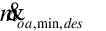 using the density of dry air at
20 degrees C. If the economizer is on an air loop then the
minimum outside air flow fraction is initialized to:
using the density of dry air at
20 degrees C. If the economizer is on an air loop then the
minimum outside air flow fraction is initialized to:
Where  is the design
supply air mass flow rate. If the economizer is not on an air
loop the minimum outside air flow fraction is initialized
to:
is the design
supply air mass flow rate. If the economizer is not on an air
loop the minimum outside air flow fraction is initialized
to:
where 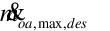 is the user input
maximum outside air volumetric flow rate converted to mass
flow rate in the same manner as for the minimum outside air
flow rate. If a minimum outside air schedule has been input,
is the user input
maximum outside air volumetric flow rate converted to mass
flow rate in the same manner as for the minimum outside air
flow rate. If a minimum outside air schedule has been input,
 is multiplied by the current
schedule value.
is multiplied by the current
schedule value.
Step
2: calculate an initial outside air signal[LINK]
We now define an initial outside air signal  .
.
If 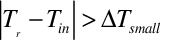 then:
then:
 .
.
Otherwise:
if 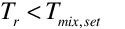 and
and  , is set to -1;
if 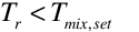 and
and  , is set to 1;
if  and
and  , is set to 1;
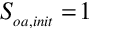
if 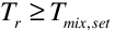 and
and  , is set to -1.
Finally, is constrained
to be:  . Basically, if the
outside air can not accomplish cooling, is set to
. Basically, if the
outside air can not accomplish cooling, is set to  . If it can do cooling, is greater than the minimum
outside air flow fraction but not greater than1. Here
. If it can do cooling, is greater than the minimum
outside air flow fraction but not greater than1. Here
Tr~~ is the return air temperature
[C];
Ti is the outside air inlet temperature
[C];
Tmix,set is the mixed air setpoint
[C];
 is a small
temperature difference [delta C], equal to .00001.
is a small
temperature difference [delta C], equal to .00001.
Step 3: do the
on/off and limit checks[LINK]
If EconomizerChoice = No Economizer,  .
.
If  ,
,  ;
;  is.001 m3/s.
If the economizer is locked out,  .
.
Note: the above three checks also set the
EconomizerOperationFlag and
HighHumidityControlFlag to false (economizer
and high humidity control not operating).
If 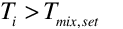 ,
,  .
.
If Differential dry-bulb was input as Economizer choice and
 , then
  .
.
If Differential Enthalpy was input as Economizer choice and
 , then
  , where hi
and hr are the outside air inlet and
return air enthalpies.
, where hi
and hr are the outside air inlet and
return air enthalpies.
Setpoints are checked after this which include check for
Fixed dry-bulb temperature limit, Enthalpy Limit, Dewpoint
Limit and Humidity ratio limit if specified.
If Differential Enthalpy was input as Economizer choice and
, then , where hi
and hr are the outside air inlet and
return air enthalpies.
Setpoints are checked after this which include check for
Fixed dry-bulb temperature limit, Enthalpy Limit, Dewpoint
Limit and Humidity ratio limit if specified.
If a FixedDryBulb / FixedEnthalpy / FixedDewPointAndDryBulb
/ ElectronicEnthalpy was input as the economizer choice then
the limits are checked as before.
Limits are checked as follows
If a high temperature limit was input and  ,
,  ; where
Toa is the outside air temperature.
; where
Toa is the outside air temperature.
If an enthalpy limit was input and 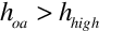 ,
,  ; where hoa
is the outside air specific enthalpy.
; where hoa
is the outside air specific enthalpy.
If a dewpoint temperature limit was input and  , ; where TDP,OA is the
outside air dewpoint temperature and TDP,high is
dewpoint temperature limit.
, ; where TDP,OA is the
outside air dewpoint temperature and TDP,high is
dewpoint temperature limit.
If an electronic enthalpy curve was input and  , ; where wOA
is the outside air humidity ratio and
wCurveOutput is the curve’s humidity ratio
output as a function of outdoor air dry-bulb temperature.
, ; where wOA
is the outside air humidity ratio and
wCurveOutput is the curve’s humidity ratio
output as a function of outdoor air dry-bulb temperature.
Another Economizer choice called
DifferentialDryBulbAndEnthalpy checks the outside air
temperature against return temperature and outside air
enthalpy against return air enthalpy and also checks the
setpoints.
If a low temperature limit was input and 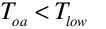 ,
,  .
.
Note: the above nine cases set the
EconomizerOperationFlag to false (economizer
not operating), otherwise the economizer is active.
If high humidity control is specified and the zone
humidistat indicates a moisture load (i.e. zone relative
humidity greater than the relative humidity setpoint), the
HighHumidityOperationFlag is set to true. If
high humidity control is based on the outdoor humidity ratio
then the HighHumidityOperationFlag is set to
true only when the outdoor air humidity ratio is less
than the humidstat’s zone humidity ratio. A true
HIghHumidityOperationFlag also enables economizer operation in
the heat exchangers as if the economizer flag used here was
also set to true (Ref. HeatExchanger:* - field
Economizer Lockout).
The economizer schedule is then checked to determine if a
“push-button” type economizer control is used. When schedule
values are greater than 0, the economizer is active
(EconomizerOperationFlag = true). This test
overrides the economizer limit checks described above in Step
3.
Step 4:
calculate the final outside air signal[LINK]
If Soa,init is greater than and less than 1 and the mixed air
mass flow rate is greater than 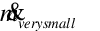 (
( ) and night venting is not
occuring and HighHumidityOperationFlag is false
then
) and night venting is not
occuring and HighHumidityOperationFlag is false
then
we calculate a final outside air signal
Soa by using the regula falsi method
routine SolveRegulaFalsi to zero the residual 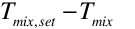 by varying the outside air mass
flow rate
by varying the outside air mass
flow rate 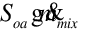 . Mass and energy
balance are used to obtain the mixed air humidity ratio and
enthalpy from the recirculated air and outside air inlet
conditions. The psychrometric function PsyTdbFnHW is
used to obtain Tmix from the mixed air
enthalpy and humidity ratio.
. Mass and energy
balance are used to obtain the mixed air humidity ratio and
enthalpy from the recirculated air and outside air inlet
conditions. The psychrometric function PsyTdbFnHW is
used to obtain Tmix from the mixed air
enthalpy and humidity ratio.
Otherwise
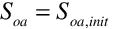 .
.
Step
5: calculate the outside air flow rate and apply final
constraints[LINK]
If BypassChoice =True and
HighHumidityOperationFlag = false,  .
.
If the HighHumidityOperationFlag is true
then
If night ventilation is occuring, 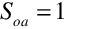 .(Night Ventilation has priority
over the above constraints)
.(Night Ventilation has priority
over the above constraints)
If the Minimum Outside air flow Schedule and the Maximum
outside air flow schedule is available , Out Air signal S
oa,init is checked against those fractions from
the schedule.
Soa = Maximum( Minimum OA fraction,
Soa)
Soa = Minimum(Maximum OA fraction,
Soa)
Now the outside air flow rate is calculated:
Calculate the outside air mass flow rate:
If EconomizerOperationFlag is true and
HighHumidityOperationFlag is false then
Otherwise
Then the following constraints are applied.
 must be greater than or
equal to the air primary loop total exhaust air mass flow rate
(
must be greater than or
equal to the air primary loop total exhaust air mass flow rate
( ).
).
If MinimumLimit = Fixed Minimum,  must be greater than or equal to
the minimum outside air mass flow rate.
must be greater than or equal to
the minimum outside air mass flow rate.
 must be
  .
.
 must be
  the maximum outside air mass flow
rate.
the maximum outside air mass flow
rate.
If heat recovery bypass control is selected, the type of
control determines how heat recovery is simulated. If
BypassWhenWithinEconomizerLimits is selected, heat recovery is
only active when the EconomizerOperationFlag is false. If
BypassWhenOAFlowGreaterThanMinimum is selected and
the EconomizerOperationFlag is true and the outside
air mass flow rate is greater than the minimum flow rate, heat
recovery is disabled, otherwise heat recovery is active. The
heat recovery bypass control option is used to optimize heat
recovery in heating mode. Heat recovery is commonly used to
reduce the cooling load when outdoor conditions are higher
than indoor conditions, however, when outdoor conditions are
favorable the heat exchanger can be turned off and the
economizer may be used to also reduce the cooling load.
Economizer mode is typically involves increasing the outdoor
air flow rate. At some point the outdoor air flow rate must be
reduced and the heat exchanger should be turned back on to
reduce or avoid an indoor heating requirement. This option
will typically be used with some form of supply air
temperature control used with the heat recovery equipment
(Ref. HeatExchanger).
Step 6: set
the relief air mass flow rate[LINK]
Outdoor
Air Damper Controller for Zone Energy Recovery Ventilator[LINK]
The stand alone energy recovery ventilator (ERV) controller
is used solely in conjunction with a stand alone energy
recovery ventilator (see figure below).
This controller object mimics virtually all of the control
logic available for a conventional air-side economizer as
embodied in the object Controller:OutdoorAir.
However, this controller is only used with the stand alone
energy recovery ventilator object (dedicated to serving a
single zone, without a traditional air distribution system)
while the Controller:OutdoorAir
is used with systems that utilize an air loop to provide
conditioned air to one or more zones. The purpose of this
controller is to signal the object HeatExchanger:AirToAir:SensibleAndLatent
that favorable conditions are available for free cooling and
heat exchange should be suspended (i.e., air flow is fully
bypassed around a fixed-plate heat exchanger or the rotation
of a rotary heat exchanger is stopped). A time-of-day schedule
may also be used to simulate a “push-button” type economizer.
The air flow rate through the stand alone ERV remains the same
regardless of whether the controller is signaling for
economizer (free cooling) operation or not. In this way, this
controller is very similar to Controller:OutdoorAir
with the field Economizer Control Action Type set to
“MinimumFlowWithBypass”. However, the supply and exhaust air
flow rates may be modified in response to a high indoor
humidity condition (i.e., when the zone relative humidity is
“predicted” to exceed the setpoint, at times the actual zone
relative humidity may be slightly below the setpoint. Ref.
Zone/Sys Moisture Load Rate Predicted.) and works in a similar
fashion to the outside air controller where the air flow rates
are adjusted based on a user specified air flow
ratio.
Controller Logic[LINK]
In many ways, the logic for this controller follows that
established for the object Controller:OutdoorAir.
Nearly the same computations (source code) are used for this
controller as for Controller:OutdoorAir,
except the addition of a few calculations that are unique for
this stand alone ERV controller. Refer to the
Simulation discussion for the outdoor air controller
to review the calculation procedure. In some instances local
variables used in the Controller:OutdoorAir
computations are set to specific values for ZoneHVAC:EnergyRecoveryVentilator:Controller
to allow the same computations and logic to be used for both
controllers. The logic that is being applied for ZoneHVAC:EnergyRecoveryVentilator:Controller
is presented below.
As explained above the controller senses when air
conditions are such that heat exchange by the air-to-air heat
exchanger should be suspended to provide free cooling to the
zone, thereby reducing the amount of mechanical cooling that
needs to be provided by other equipment. The inputs for this
controller specify temperature and/or enthalpy conditions that
are used to trigger economizer operation. An economizer
lockout input is provided in the heat exchanger object and is
used for customizing heat exchanger performance during
economizer operation. Heat exchange is suspended only if the
heat exchanger’s economizer lockout input is set to Yes.
The user can enter a high and low temperature limit for
economizer operation. When the supply inlet (outdoor) air is
between these two values, heat exchange is suspended while air
flow rates remain unchanged. This logic represents a
conventional single-point temperature economizer control. If
the user wishes to model differential temperature control,
EXHAUST AIR TEMP LIMIT should be specified in the proper input
field. In this case, heat exchange is suspended whenever the
temperature of the exhaust air is greater than the temperature
of the outdoor air. The user still needs to set the low
temperature limit to restart the heat exchange process when
the outdoor temperature falls too low.
A high dewpoint temperature limit may also be specified.
When the supply inlet (outdoor) air is below this limit, heat
exchange is suspended while air flow rates remains unchanged.
The user still needs to set the low temperature limit to
restart the heat exchange process when the outdoor temperature
falls too low.
Similar logic can be used with air enthalpy. The user can
enter a high enthalpy limit, and heat exchange between the
supply and exhaust air streams will be suspended when the
outdoor air enthalpy falls below this value. This logic
represents single-point enthalpy economizer control. If the
user wishes to model differential enthalpy control, EXHAUST
AIR ENTHALPY LIMIT should be specified in the proper input
field. Regardless of modeling single-point enthalpy or
differential enthalpy control, the user still needs to set the
low temperature limit to restart the heat exchange process
when the outdoor temperature falls too low.
The user may also specify an electronic enthalpy curve
object to represent a variable enthalpy controller. A
quadratic or cubic curve is used in this case. The output of
this curve would represent the maximum outdoor humidity ratio
allowed as a function of outdoor dry-bulb temperature.
The air flow rates through the stand alone ERV may also be
modified based on a high indoor relative humidity condition.
The change in air flow rates may occur at any time the indoor
relative humidity is high or when the indoor relative humidity
is high and the outdoor humidity ratio is lower than
the indoor humidity ratio. This control mode modifies the air
flow rates according to the user specified high humidity
outside air flow ratio. When high humidity control is active,
heat exchange is suspended in the same manner as if an
economizer were used and, as with economizer operation, heat
exchange is suspended only if the heat exchanger’s economizer
lockout input is set to Yes.
The model is flexible, and checks all limits established by
the user in the object’s input data. The model initially
assumes that heat exchange should be suspended, and then
checks each one of the limits that the user has set
(single-point temperature, differential temperature,
single-point enthalpy and differential point enthalpy,
single-point dewpoint or electronic (variable) enthalpy). If
any of the limits entered by the user is exceeded, then
economizer operation is terminated and heat exchange between
the supply and exhaust air streams is modeled.

HVAC Controllers[LINK]
Control Valve for Water-Based Air System Coils[LINK]
The input object Controller:WaterCoil provides a simple controller model for adjusting water flow rates to meet the desired air side conditions. It is really a solution inverter. For a water coil the simulation cannot be inverted where the mass flow rate of the water through the coil can be solved directly given an air temperature. Thus, this “controller” will numerically step through all of the water flow possibilities by a root finding technique until the mass flow rate is determined to meet the specified outlet air temperature within a specified user tolerance.
Model Description[LINK]
The figure below illustrates the use of a simple controller used with a central chilled water coil (control variable Temperature). The controller reads the desired temperature setpoint from the control node (established by a SetpointManager) and modulates the chilled water flow rate at the actuator node in order to meet the desired supply (coil outlet) air temperature.
In this case, the controller simply senses the temperature at the control node and compares this value with the desired temperature setpoint. If the sensed temperature is above the desired setpoint temperature, the chilled water flow rate is increased. This controller may be used for both chilled water and hot water coils. The action parameter input is set to REVERSE for chilled water cooling coils and NORMAL for hot water heating coils.
The simple controller may also be used to control both high temperature and high humidity levels by controlling the water flow rate through a chilled water coil. Setting the controller’s control variable to TemperatureAndHumidityRatio enables this feature. In this case, the controller monitors two setpoint values, one for temperature control and the other for high humidity control. Note that two setpoint managers must be used to establish these setpoints as shown in the figure below. The limiting case for either temperature or high humidity control (i.e., the minimum supply air temperature required to meet both setpoints) is used for controlling the water flow rate through the chilled water coil. If high humidity control is the limiting case then colder supply air will be delivered by the cooling coil to achieve proper dehumidification and some form of air reheat may be required to avoid overcooling of the zones being served by this air loop.
When the control variable TemperatureAndHumidityRatio is used, the controller modulates water flow through a chilled water coil to meet both a temperature and a humidity ratio setpoint. These two setpoints are placed on the control node by setpoint managers.
The model first calculates the approach temperature using the dry-bulb temperature and dewpoint temperature of the air leaving the water coil:
where:
The supply air dewpoint temperature required to meet the humidity ratio setpoint (placed on the control node by SetpointManager:SingleZone:Humidity:Maximum, SetpointManager:MultiZone:MaximumHumidity:Average or SetpointManager:MultiZone:Humidity:Maximum) is then calculated as a function of the humidity ratio setpoint and barometric pressure as follows:
where:
In order for the dewpoint temperature of the coil’s supply (outlet) air to reach the
dry-bulb temperature of air leaving the cooling coil must be
at
the
dry-bulb temperature of air leaving the cooling coil must be
at  :
:
where:
The supply air temperature setpoint required to achieve the specified humidity ratio setpoint is then compared to the setpoint temperature required for zone temperature control, and the minimum of these two setpoint values is used as the setpoint temperature for controlling the chilled water coil.
where:
As described previously, the controller varies the chilled water flow rate through the coil using a root finding technique until the actual supply air temperature reaches Tspwithin the specified tolerance:
where:
Outdoor Air Damper Controller for Air Systems[LINK]
When the heat exchanger assisted cooling coil is used with a furnace or unitary system (ref. AirLoopHVAC:Unitary:Furnace:HeatCool or AirLoopHVAC:UnitaryHeatCool) or DX system (ref. CoilSystem:Cooling:DX) located in an air loop (or DX system used in an outside air system), an ecomizier function may be customized as necessary. For economizer control, an outdoor air controller (ref. Controller:OutdoorAir) is used to define the economizer control inputs and determine when economizer mode is active. The heat exchanger (ref. HeatExchanger:*) object provides an economizer lockout feature which disables heat recovery any time the economizer is active. This feature can be turned on and off using the heat exchanger lockout input. Heat exchanger assisted cooling coils used with the zone equipment described below disregard this economizer control feature. The heat recovery bypass control input may also be used to selectively control heat recovery.
Inputs[LINK]
Controller Name
Relief air node
Return air node
Control node (the mixed air node)
Actuated node (the outside air inlet node)
Minimum outside air flow rate (at design) [m3/s]
Maximum outside air flow rate ( ) [m3/s]
EconomizerChoice: FixedDryBulbr | FixedEnthalpy | DifferentialDryBulb | DifferentialEnthalpy | ElectronicEnthalpy | FixedDewPointAndDryBulb | DifferentialDryBulbAndEnthalpy | NoEconomizer
Bypasschoice: MinimumFlowWithBypass | ModulateFlow
High temperature limit ( )
[C]
)
[C]
High specific enthalpy limit ( ) [J/kg]
High dewpoint temperature limit ( ) [C]
) [C]
Electronic Enthalpy limit (quadratic or cubic curve object)
Low temperature limit ( )
[C]
)
[C]
Lockout: LockoutWithHeating | LockoutWithCompressor
MinimumLimit: FixedMinimum | ProportionalMinimum
Minimum outside air schedule (schedule values multiply the minimum outside air flow rate)
Minimum Outside air flow Schedule(schedule values sets the limit on minimum outside air)
Maximum Outside air flow Schedule(schedule values sets the maximum amount of outside air possible in the system)
Name of Controller:MechanicalVentilation object
Time-of-day economizer control schedule (economizer active when schedule values are greater than 0)
High humidity control flag: Yes | No
Humidstat control zone name (zone name where humidistat is located)
Control high indoor humidity based on outdoor humidity ratio: Yes | No
High humidity outside air flow ratio (this flow ratio is multiplied by the maximum outside air flow rate during periods of high indoor relative humidity)
Heat Recovery Bypass Control Type: BypassWhenWithinEconomizerLimits | BypassWhenOAFlowGreaterThanMinimum
Economizer Limits[LINK]
Economizer limits may be used to create single-point or multi-point controllers. The figure below shows several examples of each type of controller. Single-point economizer controllers use a single independent variable to specify the operation of the economizer. In all cases, the economizer is disabled (OFF) when the outdoor weather condition exceeds the limit. However, when a low temperature limit is used the economizer is disabled when the outdoor temperature is below the low dry-bulb temperature limit.
Economizer limits may also be used to create multi-point controllers where two or more limits specify the economizer operating region. The economizer is disabled (OFF) if any single multi-point economizer limit is exceeded.
Simulation[LINK]
The simulation contains 4 steps.
Step 1: calculate the minimum outside air flow rate[LINK]
The user inputs the minimum outside air flow rate (or it is automatically calculated by the program from the user’s design inputs). This is converted to a mass flow rate using the density of dry air at
20 degrees C. If the economizer is on an air loop then the
minimum outside air flow fraction is initialized to:
using the density of dry air at
20 degrees C. If the economizer is on an air loop then the
minimum outside air flow fraction is initialized to:
Where is the design
supply air mass flow rate. If the economizer is not on an air
loop the minimum outside air flow fraction is initialized
to:
is the design
supply air mass flow rate. If the economizer is not on an air
loop the minimum outside air flow fraction is initialized
to:
where is the user input
maximum outside air volumetric flow rate converted to mass
flow rate in the same manner as for the minimum outside air
flow rate. If a minimum outside air schedule has been input,
is the user input
maximum outside air volumetric flow rate converted to mass
flow rate in the same manner as for the minimum outside air
flow rate. If a minimum outside air schedule has been input,
 is multiplied by the current
schedule value.
is multiplied by the current
schedule value.
Step 2: calculate an initial outside air signal[LINK]
We now define an initial outside air signal .
.
If then:
then:
Otherwise:
if and
and  ,
,  is set to -1;
if and
and  ,
,  is set to 1;
if and
and  ,
,  is set to 1;
if and
and  ,
,  is set to -1.
Finally, is constrained
to be:
is constrained
to be:  . Basically, if the
outside air can not accomplish cooling,
. Basically, if the
outside air can not accomplish cooling,  is set to
  . If it can do cooling,
  is greater than the minimum
outside air flow fraction but not greater than1. Here
is greater than the minimum
outside air flow fraction but not greater than1. Here
Tr~~ is the return air temperature [C];
Ti is the outside air inlet temperature [C];
Tmix,set is the mixed air setpoint [C];
Step 3: do the on/off and limit checks[LINK]
If EconomizerChoice = No Economizer, .
.
If ,
,  ;
;  is.001 m3/s.
If the economizer is locked out, .
.
Note: the above three checks also set the EconomizerOperationFlag and HighHumidityControlFlag to false (economizer and high humidity control not operating).
If ,
,  .
.
If Differential dry-bulb was input as Economizer choice and , then
  .
.
If Differential Enthalpy was input as Economizer choice and , then
  , where hi
and hr are the outside air inlet and
return air enthalpies.
, where hi
and hr are the outside air inlet and
return air enthalpies.
Setpoints are checked after this which include check for Fixed dry-bulb temperature limit, Enthalpy Limit, Dewpoint Limit and Humidity ratio limit if specified.
If Differential Enthalpy was input as Economizer choice and , then
  , where hi
and hr are the outside air inlet and
return air enthalpies.
, where hi
and hr are the outside air inlet and
return air enthalpies.
Setpoints are checked after this which include check for Fixed dry-bulb temperature limit, Enthalpy Limit, Dewpoint Limit and Humidity ratio limit if specified.
If a FixedDryBulb / FixedEnthalpy / FixedDewPointAndDryBulb / ElectronicEnthalpy was input as the economizer choice then the limits are checked as before.
Limits are checked as follows
If a high temperature limit was input and ,
,  ; where
Toa is the outside air temperature.
; where
Toa is the outside air temperature.
If an enthalpy limit was input and ,
,  ; where hoa
is the outside air specific enthalpy.
; where hoa
is the outside air specific enthalpy.
If a dewpoint temperature limit was input and ,
,  ; where TDP,OA is the
outside air dewpoint temperature and TDP,high is
dewpoint temperature limit.
; where TDP,OA is the
outside air dewpoint temperature and TDP,high is
dewpoint temperature limit.
If an electronic enthalpy curve was input and ,
,  ; where wOA
is the outside air humidity ratio and
wCurveOutput is the curve’s humidity ratio
output as a function of outdoor air dry-bulb temperature.
; where wOA
is the outside air humidity ratio and
wCurveOutput is the curve’s humidity ratio
output as a function of outdoor air dry-bulb temperature.
Another Economizer choice called DifferentialDryBulbAndEnthalpy checks the outside air temperature against return temperature and outside air enthalpy against return air enthalpy and also checks the setpoints.
If a low temperature limit was input and ,
,  .
.
Note: the above nine cases set the EconomizerOperationFlag to false (economizer not operating), otherwise the economizer is active.
If high humidity control is specified and the zone humidistat indicates a moisture load (i.e. zone relative humidity greater than the relative humidity setpoint), the HighHumidityOperationFlag is set to true. If high humidity control is based on the outdoor humidity ratio then the HighHumidityOperationFlag is set to true only when the outdoor air humidity ratio is less than the humidstat’s zone humidity ratio. A true HIghHumidityOperationFlag also enables economizer operation in the heat exchangers as if the economizer flag used here was also set to true (Ref. HeatExchanger:* - field Economizer Lockout).
The economizer schedule is then checked to determine if a “push-button” type economizer control is used. When schedule values are greater than 0, the economizer is active (EconomizerOperationFlag = true). This test overrides the economizer limit checks described above in Step 3.
Step 4: calculate the final outside air signal[LINK]
If Soa,init is greater than and less than 1 and the mixed air
mass flow rate is greater than
and less than 1 and the mixed air
mass flow rate is greater than  (
( ) and night venting is not
occuring and HighHumidityOperationFlag is false
then
) and night venting is not
occuring and HighHumidityOperationFlag is false
then
we calculate a final outside air signal Soa by using the regula falsi method routine SolveRegulaFalsi to zero the residual by varying the outside air mass
flow rate
by varying the outside air mass
flow rate  . Mass and energy
balance are used to obtain the mixed air humidity ratio and
enthalpy from the recirculated air and outside air inlet
conditions. The psychrometric function PsyTdbFnHW is
used to obtain Tmix from the mixed air
enthalpy and humidity ratio.
. Mass and energy
balance are used to obtain the mixed air humidity ratio and
enthalpy from the recirculated air and outside air inlet
conditions. The psychrometric function PsyTdbFnHW is
used to obtain Tmix from the mixed air
enthalpy and humidity ratio.
Otherwise
Step 5: calculate the outside air flow rate and apply final constraints[LINK]
If BypassChoice =True and HighHumidityOperationFlag = false, .
.
If the HighHumidityOperationFlag is true then
If night ventilation is occuring, .(Night Ventilation has priority
over the above constraints)
.(Night Ventilation has priority
over the above constraints)
If the Minimum Outside air flow Schedule and the Maximum outside air flow schedule is available , Out Air signal S oa,init is checked against those fractions from the schedule.
Soa = Maximum( Minimum OA fraction, Soa)
Soa = Minimum(Maximum OA fraction, Soa)
Now the outside air flow rate is calculated:
Calculate the outside air mass flow rate:
If EconomizerOperationFlag is true and HighHumidityOperationFlag is false then
Otherwise
Then the following constraints are applied.
If MinimumLimit = Fixed Minimum, must be greater than or equal to
the minimum outside air mass flow rate.
must be greater than or equal to
the minimum outside air mass flow rate.
If heat recovery bypass control is selected, the type of control determines how heat recovery is simulated. If BypassWhenWithinEconomizerLimits is selected, heat recovery is only active when the EconomizerOperationFlag is false. If BypassWhenOAFlowGreaterThanMinimum is selected and the EconomizerOperationFlag is true and the outside air mass flow rate is greater than the minimum flow rate, heat recovery is disabled, otherwise heat recovery is active. The heat recovery bypass control option is used to optimize heat recovery in heating mode. Heat recovery is commonly used to reduce the cooling load when outdoor conditions are higher than indoor conditions, however, when outdoor conditions are favorable the heat exchanger can be turned off and the economizer may be used to also reduce the cooling load. Economizer mode is typically involves increasing the outdoor air flow rate. At some point the outdoor air flow rate must be reduced and the heat exchanger should be turned back on to reduce or avoid an indoor heating requirement. This option will typically be used with some form of supply air temperature control used with the heat recovery equipment (Ref. HeatExchanger).
Step 6: set the relief air mass flow rate[LINK]
Outdoor Air Damper Controller for Zone Energy Recovery Ventilator[LINK]
The stand alone energy recovery ventilator (ERV) controller is used solely in conjunction with a stand alone energy recovery ventilator (see figure below).
This controller object mimics virtually all of the control logic available for a conventional air-side economizer as embodied in the object Controller:OutdoorAir. However, this controller is only used with the stand alone energy recovery ventilator object (dedicated to serving a single zone, without a traditional air distribution system) while the Controller:OutdoorAir is used with systems that utilize an air loop to provide conditioned air to one or more zones. The purpose of this controller is to signal the object HeatExchanger:AirToAir:SensibleAndLatent that favorable conditions are available for free cooling and heat exchange should be suspended (i.e., air flow is fully bypassed around a fixed-plate heat exchanger or the rotation of a rotary heat exchanger is stopped). A time-of-day schedule may also be used to simulate a “push-button” type economizer. The air flow rate through the stand alone ERV remains the same regardless of whether the controller is signaling for economizer (free cooling) operation or not. In this way, this controller is very similar to Controller:OutdoorAir with the field Economizer Control Action Type set to “MinimumFlowWithBypass”. However, the supply and exhaust air flow rates may be modified in response to a high indoor humidity condition (i.e., when the zone relative humidity is “predicted” to exceed the setpoint, at times the actual zone relative humidity may be slightly below the setpoint. Ref. Zone/Sys Moisture Load Rate Predicted.) and works in a similar fashion to the outside air controller where the air flow rates are adjusted based on a user specified air flow ratio.
Controller Logic[LINK]
In many ways, the logic for this controller follows that established for the object Controller:OutdoorAir. Nearly the same computations (source code) are used for this controller as for Controller:OutdoorAir, except the addition of a few calculations that are unique for this stand alone ERV controller. Refer to the Simulation discussion for the outdoor air controller to review the calculation procedure. In some instances local variables used in the Controller:OutdoorAir computations are set to specific values for ZoneHVAC:EnergyRecoveryVentilator:Controller to allow the same computations and logic to be used for both controllers. The logic that is being applied for ZoneHVAC:EnergyRecoveryVentilator:Controller is presented below.
As explained above the controller senses when air conditions are such that heat exchange by the air-to-air heat exchanger should be suspended to provide free cooling to the zone, thereby reducing the amount of mechanical cooling that needs to be provided by other equipment. The inputs for this controller specify temperature and/or enthalpy conditions that are used to trigger economizer operation. An economizer lockout input is provided in the heat exchanger object and is used for customizing heat exchanger performance during economizer operation. Heat exchange is suspended only if the heat exchanger’s economizer lockout input is set to Yes.
The user can enter a high and low temperature limit for economizer operation. When the supply inlet (outdoor) air is between these two values, heat exchange is suspended while air flow rates remain unchanged. This logic represents a conventional single-point temperature economizer control. If the user wishes to model differential temperature control, EXHAUST AIR TEMP LIMIT should be specified in the proper input field. In this case, heat exchange is suspended whenever the temperature of the exhaust air is greater than the temperature of the outdoor air. The user still needs to set the low temperature limit to restart the heat exchange process when the outdoor temperature falls too low.
A high dewpoint temperature limit may also be specified. When the supply inlet (outdoor) air is below this limit, heat exchange is suspended while air flow rates remains unchanged. The user still needs to set the low temperature limit to restart the heat exchange process when the outdoor temperature falls too low.
Similar logic can be used with air enthalpy. The user can enter a high enthalpy limit, and heat exchange between the supply and exhaust air streams will be suspended when the outdoor air enthalpy falls below this value. This logic represents single-point enthalpy economizer control. If the user wishes to model differential enthalpy control, EXHAUST AIR ENTHALPY LIMIT should be specified in the proper input field. Regardless of modeling single-point enthalpy or differential enthalpy control, the user still needs to set the low temperature limit to restart the heat exchange process when the outdoor temperature falls too low.
The user may also specify an electronic enthalpy curve object to represent a variable enthalpy controller. A quadratic or cubic curve is used in this case. The output of this curve would represent the maximum outdoor humidity ratio allowed as a function of outdoor dry-bulb temperature.
The air flow rates through the stand alone ERV may also be modified based on a high indoor relative humidity condition. The change in air flow rates may occur at any time the indoor relative humidity is high or when the indoor relative humidity is high and the outdoor humidity ratio is lower than the indoor humidity ratio. This control mode modifies the air flow rates according to the user specified high humidity outside air flow ratio. When high humidity control is active, heat exchange is suspended in the same manner as if an economizer were used and, as with economizer operation, heat exchange is suspended only if the heat exchanger’s economizer lockout input is set to Yes.
The model is flexible, and checks all limits established by the user in the object’s input data. The model initially assumes that heat exchange should be suspended, and then checks each one of the limits that the user has set (single-point temperature, differential temperature, single-point enthalpy and differential point enthalpy, single-point dewpoint or electronic (variable) enthalpy). If any of the limits entered by the user is exceeded, then economizer operation is terminated and heat exchange between the supply and exhaust air streams is modeled.
Documentation content copyright © 1996-2026 The Board of Trustees of the University of Illinois and the Regents of the University of California through the Ernest Orlando Lawrence Berkeley National Laboratory. All rights reserved. EnergyPlus is a trademark of the US Department of Energy.
This documentation is made available under the EnergyPlus Open Source License v1.0.